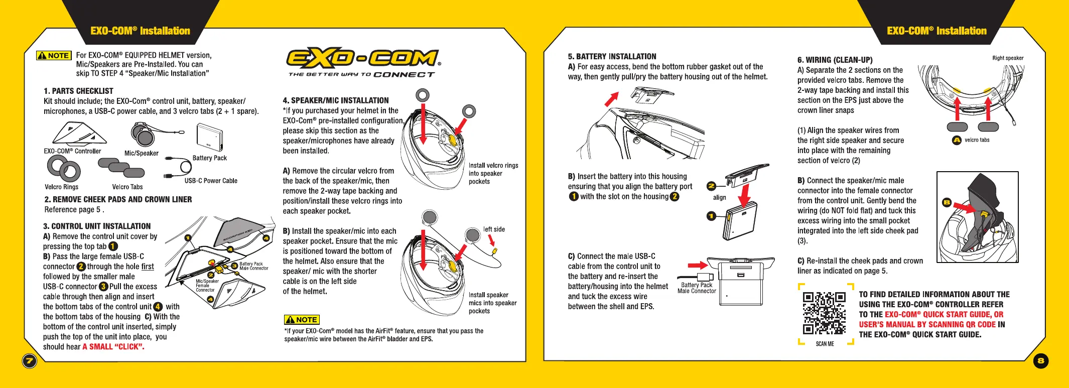
IA NOTE I For EXO-COM® EQUIPPED HELMET version,
Mic/Speakers are Pre-Installed. You can
skip TO STEP 4 "Speaker/Mic Installation"
1. PARTS CHECKLIST
Kit should include; the EXO-Com® control unit, battery, speaker/
microphones, a USB-C power cable, and 3 velcro tabs (2
+ 1 spare).
~~
EXO-COM® Controller
Mic/Speaker
.:D Battery Pack
USB-C Power Cable
Velcro Rings
Velcro Tabs
2. REMOVE CHEEK PADS AND CROWN LINER
Reference page 5 .
3. CONTROL UNIT INSTALLATION
A) Remove the control unit cover by
pressing the top tab
0
B) Pass the large female USB-C
connector f)through the hole first
followed by the smaller male
USB-C connectorE)Pull the excess
cable through then align and insert
the bottom tabs of the control
unitO with
the bottom tabs of the housing C) With the
bottom of the control unit inserted, simply
push the top of the unit into place, you
should hear
A SMALL "CLICK".
THE BETTER WFIY TD CONNECT
4. SPEAKER/MIC INSTALLATION
*If you purchased your helmet in the
EXO-Com® pre-installed configuration,
please skip this section as the
speaker/microphones have already
been installed.
A) Remove the circular velcro from
the back of the speaker/mic, then
remove the 2-way tape backing and
position/install these velcro rings into
each speaker pocket.
B) Install the speaker/mic into each
speaker pocket. Ensure that the mic
is positioned toward the bottom of
the helmet. Also ensure that the
speaker/ mic with the shorter
cable is on the left side
of the helmet.
IANOTEI
Install velcro rings
into speaker
pockets
/ Install speaker
mies into speaker
pockets
*If your EXO-Com® model has the AirFit® feature, ensure that you pass the
speaker/mic wire between the AirFit® bladder and EPS.
o.,___ _______________ ___,
5. BATTERY INSTALLATION
A) For easy access, bend the bottom rubber gasket out of the
way, then gently pull/pry the battery housing out of the helmet.
B) Insert the battery into this housing
ensuring that you align the battery port
Owith the slot on the housing@
C) Connect the male USB-C
cable from the control unit to
the battery and re-insert the
battery/housing into the helmet
and tuck the excess wire
between the shell and EPS.
....
~
---c:::::n ieei
Battery Pack
Male Connector
0
6. WIRING (CLEAN-UP)
A) Separate the 2 sections on the
provided velcro tabs. Remove the
2-way tape backing and install this
section on the EPS just above the
crown liner snaps
\/7/./1 /,{\\\
\ii'/
\j
(1) Align the speaker wires from
the right side speaker and secure
into place with the remaining
section of velcro (2)
B) Connect the speaker/mic male
connector into the female connector
from the control unit. Gently bend the
wiring (do NOT fold flat) and tuck this
excess wiring into the small pocket
integrated into the left side cheek pad
(3).
C) Re-install the cheek pads and crown
liner as indicated on page 5.
\ ~.
Right speaker
",:,,.~
~
-- . -~~~~~------
C) C)
0 velcro tabs
II
l!l ,·
TO FIND DETAILED INFORMATION ABOUT THE
USING THE EXO-COM® CONTROLLER REFER
TO THE EXO-COM® QUICK START GUIDE, OR
USER'S MANUAL BY SCANNING QR CODE IN
THE EXO-COM® QUICK START GUIDE.
SCAN ME
0
US
US
 Loading...