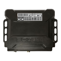
3. Diagram of the interface connector
Scheme of the interface connector (view from the side of the tracker contacts) (Figure 2):
key
Figure 2. MT-855 ENT Interface Connector
Table 3.
Universal port 0 (P0+ D, F, C, A)
Universal port 2 (P2+ D, F, C, A)
Universal port 1 (P1+ D, F, C, A)
Universal port 3 (P3- 1W, D, F, C)
4. Installation requirements
•
All actions during installation must be carried out ONLY WITH THE POWER
OFF!
•
Do not install the tracker in places subject to increased heat - this
may lead to failure of the backup battery!
•
The GPS/GLONASS antenna must be placed at least 0.5 m from the Terminal.
•
Before installation, you must install at least one SIM-card in the SIM1 slot and
connect the battery (if any)
5. Preliminary setting of the Terminal
The tracker can be configured in several ways: using the SCOUT-Configurator software,
connecting to the tracker via USB, via the Internet or using SMS commands.
To configure the tracker, you will need the SCOUT-Configurator software. This software requires
a computer with Windows 10 operating system or newer.
SCOUT-Configurator, Documentation and drivers you can download at this link
or QR code https://8xx.scout-gps.ru/mt855ent/
Before installation, the following minimum set of parameters must be configured:
Connection settings to
the telematics Server:
− Server address,
− Port,
− Server communication
protocol
− login,
− password,
− APN (access point)
− make settings depending on the
connected sensors and devices
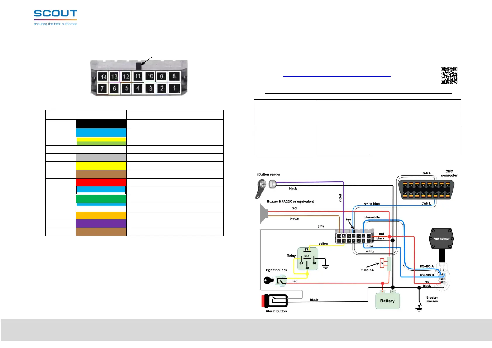
6. Typical installation scheme
 Loading...