Operation & Maintenance Manual──LG918 Wheel Loader
101
CHAPTER V THE STRUCTURE AND
PRICIPLE OF MAIN COMPONENTS
AND SYSTEM
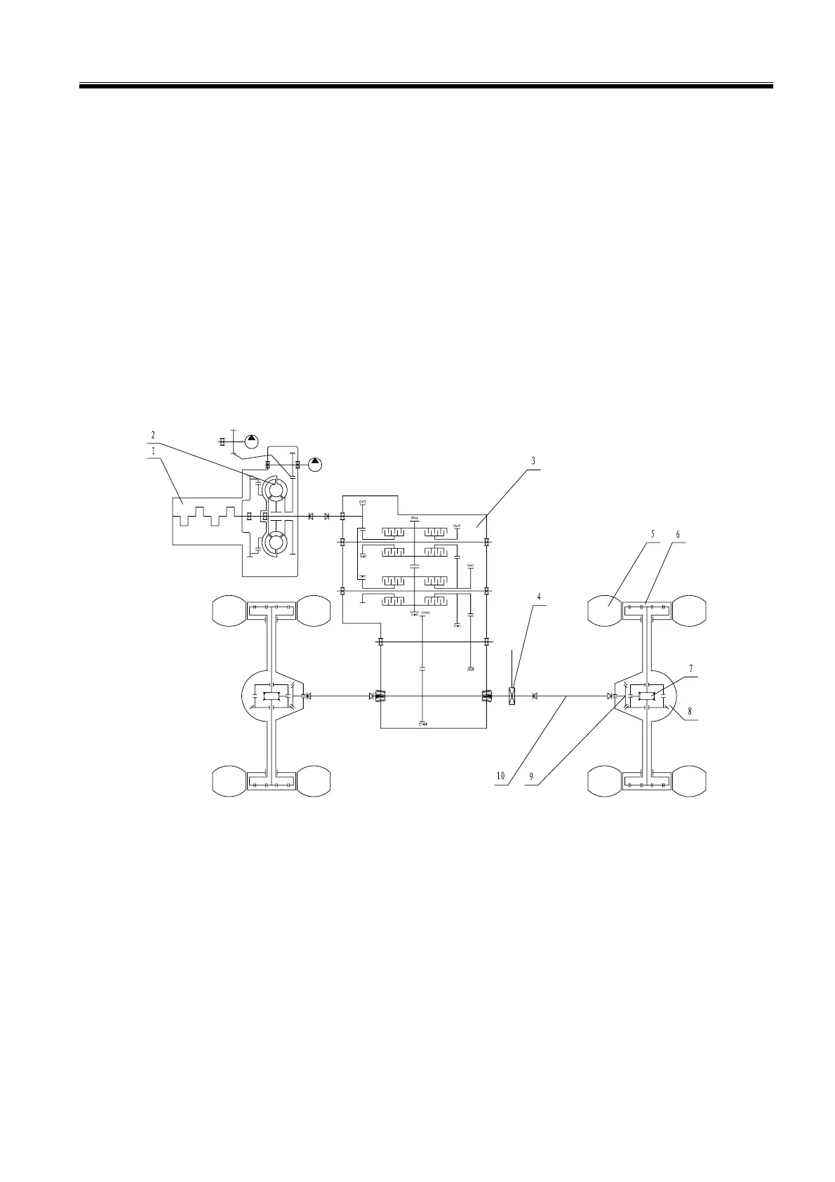
1 TRANMISSION SYSTEM
The transmission system includes the hydraulic torque converter, transmission box, the oil line system
of hydraulic torque converter of transmission box, transmission axle, front and rear driving axle,
wheel and others. The transmission system diagram is shown in the Figure 5-1.
1.Engine 2. Hydraulic Torque Converter 3. Gear Box 4. Parking Brake 5. Wheel 6. Wheel
Side Reducer 7. Differential 8. Driving Axle 9. Main Transmission 10. Transmission Shaft
Figure 5-1 LG918 Transmission System Diagram
2 HYDRAULIC SYSTEM
As shown in Figure 5-2、Figure 5-3, the hydraulic system includes the working equipment hydraulic
system and steering hydraulic system. The working equipment hydraulic system is composed of a
work pump, multi-way valve, lift arm cylinder, bucket cylinder, hydraulic pressure oil tank and pipe
attachments.

 Loading...