Operation & Maintenance Manual──LG918 Wheel Loader
51
CHAPTER III OPERATION AND
APPLICATION
1 BE FAMILIAR WITH MACHINE
1.1 Control Systems and Gauges
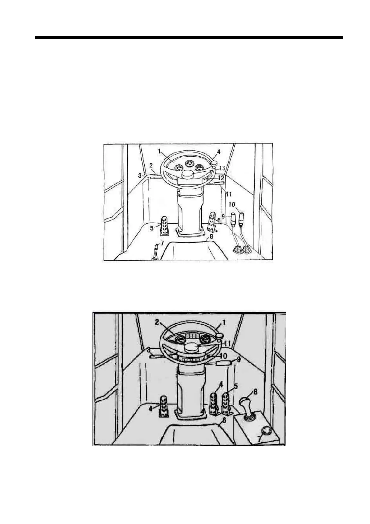
1. Panel 2. High and Low Speed Control Lever 3. Fore-and-aft Gear Control Lever
4. Steering Wheel 5. Brake Pedal 6. Accelerator Pedal 7. Parking Brake Control Lever
8. Seat 9. Bucket Control Lever 10. Lift Arm Control Lever 11. Turning Switch
12. Starting Switch 13. Horn Button
Figure 3-1 General view of control System
1. Steering Wheel 2. Panel 3. Speed Change Control Lever 4. Brake Pedal (one for left and right
side) 5. Accelerator Pedal 6. Seat 7. Parking Brake switch 8. Equipment Control Lever 9.
Switch Group 10. Starting Switch 11. Horn Button
Figure 3-2 General view of control System (with pilot single handle and three pedal)
 Loading...