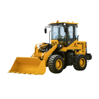
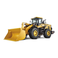
Operation & Maintenance Manual──LG958L/LG959 Wheel Loader
108
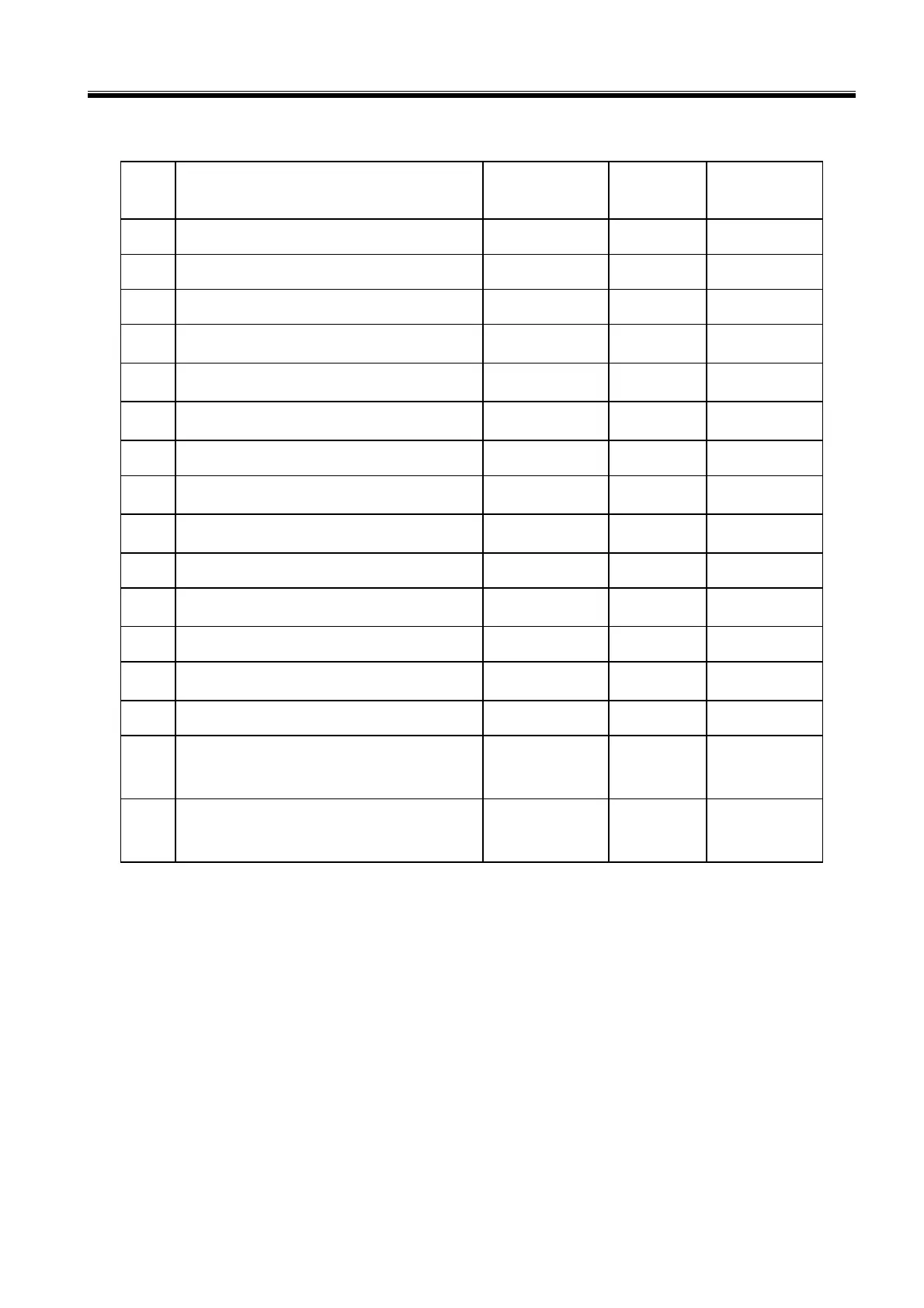
by this table except in special conditions.
No. Position Specification
Material or
character
class
Torque(N.m)
1 Fixing bolts of transmission base
M18×40 8.8 240~280
2 Middle cover bolts of transmission box
M14×35 10.9 125~165
3 Connect bolts between rim and brake plate
M20×1.5×50 8.8 280~380
4
Connect bolts of main driving left and right
differential cover
M16×1.5×150 40Cr 280~330
5
Connect bolts between main driven move
helical gear and right cover of differential
M16×1.5×55 40Cr 280~330
6
Connect bolts between main driving bearing
chock and bracket
M22×100 40Cr 500~600
7 Lock bolts of main driving input flange
M33×1.5 8 320~400
8
Connect bolts between plane frame
assembly and rim
M20×1.5 40Cr 500~600
9
Connection between the bracket of main
driving and axle shell
M16×1.5×45 8.8 193~257
10 Rim nuts
M20×1.5 35 480~580
11
Connect bolts between brake clip assembly
and stent
M20×1.5×56 40Cr 376~502
12 Assembly of driving axle and frame
M30×2×175 45 530~670
13
Supporting bolts in the middle of
transmission shaft
M14×1.5×55 8.8 125~165
14 Connection of engine oil tank and frame
M16×35 8.8 185~265
15 Connection of fuel tank and frame
M24×2×130
M24×2×80
8.8 320~480
16 Connection of dipper teeth and bucket
M20×85
M20×62
45 376~502
3 CONTENT OF MAINTENANCE
Maintenance content includes the run-in period of a new machine and the periodic maintenance of
every 10, 50, 250, 500, 1000 and 2000 hours.
3.1 Every 10 Hours (Days) Service
z Check the sealing performance of work equipment systems such as hydraulic, steering and brake
system.
z Check the flexibility and reliability of the brakes.
z Check whether the electric circuit is correct and the electric components are normal.
 Loading...