Section 09 STEERING SYSTEM
Sub-Section 04 (GS, GSI, GSX, GTI AND GTX MODELS)
09-04-5
15,16, Steering Stem Arm and Support
Position steering stem arm and support onto
steering stem.
1. Keyways
2. Integrated flat key
Replace lock nuts
no. 18
by new ones.
Torque bolts
no. 17
of steering stem arm to
6 N•m (53 lbf•
in
).
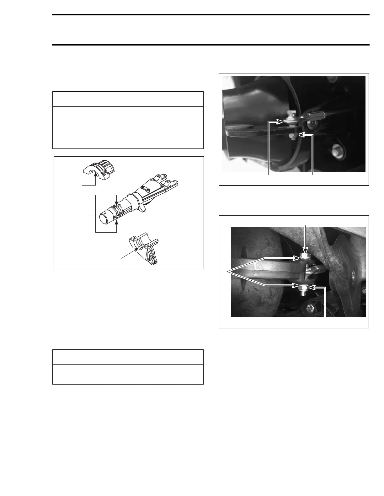
19, Ball joint
Secure the steering cable ball joint
no. 19
to the
nozzle as per following illustrations.
GSI and GSX Models
1. Ball joint on top of steering arm
2. Torque nut to 7 N•m (62 lbf•in)
GS, GTI, and GTX Models
TYPICAL
1. Bolt
2. Flat washers
3. Lock nut. Torque to 2 N•m (18 lbf•in)
STEERING ALIGNMENT
For steering alignment procedure, refer to STEER-
ING SYSTEM 09-06.
◆
WARNING
Make sure the integrated flat keys of the
steering stem arm and support are properly
seated in steering stem keyways. Steering
stem arm must be locked in place before
torquing the bolts.
-
CAUTION
Ensure the ball joint is parallel (± 5°) to the
nozzle arm.
F07K09A
2
1
2
F06K01A
1
2
F00J01A
2
1
3
 Loading...