The Seagate ST3144 Family Installation Guide, Rev. D, provides comprehensive instructions for installing and configuring Seagate ST3096A, ST3120A, and ST3144A hard disk drives. This guide is essential for users and technicians to ensure proper setup, operation, and maintenance of these AT interface drives.
Function Description
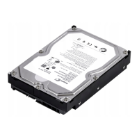
The Seagate ST3144 family of drives are hard disk drives designed for use in computer systems, primarily those with an AT interface. Their primary function is to provide non-volatile data storage. The installation guide covers the entire process from initial setup and physical mounting to software configuration, including partitioning and high-level formatting. These drives are designed to automatically park their heads at power-down, a feature that helps protect the drive from damage during movement or power loss. The guide emphasizes the importance of proper installation to ensure optimal performance and longevity of the drive. It also highlights the availability of power management options for these drives, which can be system-dependent.
Important Technical Specifications
The guide details specific geometries for the ST3096A, ST3120A, and ST3144A models, which are crucial for CMOS configuration.
-
ST3096A:
- Formatted MBytes: 89.1
- Cylinders: 1,024
- Heads: 10
- Sectors/Track: 17
- Formatted CMOS MBytes: 85.0
- Power Management Part Numbers: 911008-0XX, 911008-1XX, 911008-4XX, 911008-6XX
- Without Power Management Part Numbers: 911008-3XX, 911008-5XX
-
ST3120A:
- Formatted MBytes: 106.9
- Cylinders: 1,024
- Heads: 12
- Sectors/Track: 17
- Formatted CMOS MBytes: 102.0
- Power Management Part Numbers: 911003-0XX, 911003-1XX, 911003-4XX, 911003-6XX
- Without Power Management Part Numbers: 911003-3XX, 911003-5XX
-
ST3144A:
- Formatted MBytes: 130.7
- Cylinders: 1,001
- Heads: 15
- Sectors/Track: 17
- Formatted CMOS MBytes: 124.6
- Power Management Part Numbers: 911006-0XX, 911006-4XX, 911006-6XX
- Without Power Management Part Numbers: 911006-3XX, 911006-5XX
The guide also specifies compatibility with various BIOS revisions, including American Megatrends (Dated 4/90 or later), Award (Version 3.04 or higher), Quadtel (Single Drive System: Any Version; Dual Drive System: 3.04 or higher), Phoenix (BIOS Plus 286: 3.10 or higher; BIOS Plus 386: 1.10 or higher), and PhoenixBIOS (Version 1.00 or higher).
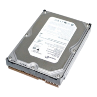
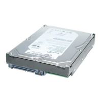
For physical connections, the drives feature a 40-pin AT Interface connector, a 4-pin DC power connector, and a 3-pin DC power connector. A 10-pin User Configuration Block is present for jumper settings, including Master/Slave configuration and Drive Activity LED. The maximum recommended cable length for the AT interface is 18 inches (457 mm). Mounting screws should be 6-32 UNC for standard-size holes ("S" stamped) or M4 for metric holes ("M" stamped), with a maximum torque of 6 inch-lbs.
Usage Features
The installation process is broken down into several key steps:
- Pre-installation Precautions: Emphasizes verifying system power is off and observing static discharge precautions (grounded wrist strap, handling by edges, avoiding I/O connector pins, using anti-static padding, avoiding carpeted areas).
- Inspection: Users are advised to check all components for damage or missing items.
- Drive Jumper Settings: Instructions are provided for configuring the drive as a Master, Slave Present, or Only drive in system using the jumper block. A Drive Activity LED jumper (pins 9 and 10) is also available.
- AT Interface Cable Attachment: Detailed instructions for connecting the 40-pin AT interface cable, ensuring Pin 1 alignment. Pin 20 is removed from the connector for keying.
- Power Cable Attachment: Connect either the 3-pin or 4-pin power cable.
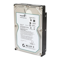
- Mounting the Drive: The drive can be mounted in any orientation, not exceeding 5° from vertical or horizontal. Specific instructions for bottom and side mounting are given, including screw types and lengths to prevent damage. A Seagate frame kit (part number 54459-016) is available for installing 3.5-inch drives into 5.25-inch frames, specifically for drives with standard-size mounting holes ("S" stamped).
- CMOS Configuration: Users must enter the drive's geometry (heads, cylinders, sectors/track) into the system's CMOS using a SETUP utility. If an exact match isn't available, selecting a "user-defined" or "custom" type, or a type with equal or lesser capacity than the "Formatted CMOS Megabytes" column, is recommended. The number of Heads multiplied by Sectors cannot exceed 255.
- Low-Level Formatting: Seagate AT interface drives are factory low-level formatted and do not require additional low-level formatting by the user.
- Partitioning: The DOS FDISK utility (DOS 3.3 or higher) is used to divide the drive into partitions. This is particularly important for DOS versions earlier than 4.0, which have capacity limitations.
- High-Level Formatting: The DOS FORMAT command is used to perform high-level formatting, which verifies the low-level format, establishes drive access information, and creates the File Allocation Table (FAT).
- Troubleshooting: A dedicated section covers common installation problems, including verifying compatibility, configuration, cable connections, card seating, power supply specifications, consistent DOS versions, CMOS drive type, and checking for viruses.
Maintenance Features
The guide explicitly states that Seagate drives do not require any preventive maintenance. The head/disc assembly is sealed and contains no user-serviceable components. Tampering with the factory seal voids the warranty. All repair services must be performed by authorized Seagate customer service centers; third-party repair facilities are not sanctioned.
For technical support, Seagate offers several services:
- SeaFAX (408/438-2620): An automated FAX system providing technical support information 24 hours a day.
- SeaBOARD (BBS): A Bulletin Board System accessible by modem 24 hours a day, offering specifications, documentation reprints, and utilities like FINDTYPE.EXE. Modem numbers are provided for United States/Canada, England, Germany, Singapore, and Australia. FINDTYPE.EXE helps match drive geometry with system BIOS types.
- SeaFONE (408/438-8222): An enhanced phone system with recorded technical information and live support specialists available Monday through Friday, 8:00 AM to 5:00 PM PST.
- SeaTDD (408/438-5382): A service for the deaf, allowing communication with technical support specialists Monday through Friday, 8:00 AM to 5:00 PM PST.
The guide also provides a warning regarding installing the drive in laptop systems, advising users to check the system warranty first and noting that such systems should only be serviced by trained technicians. Shipping drives requires a Seagate-approved container to avoid voiding the warranty.