3. SPECIFICATION
MODEL NO.: ................................................................DPF1
Air receiving tank ............................................................ 15ltr
Air requirement ............................................................4-6bar
Cleaning agent .........................................Chemical/Water/Air
Dimensions (W x L x H) ........................ 400 x 900 x 1120mm
Supply ................................................................. 230V~50Hz
Power ................................................................................5W
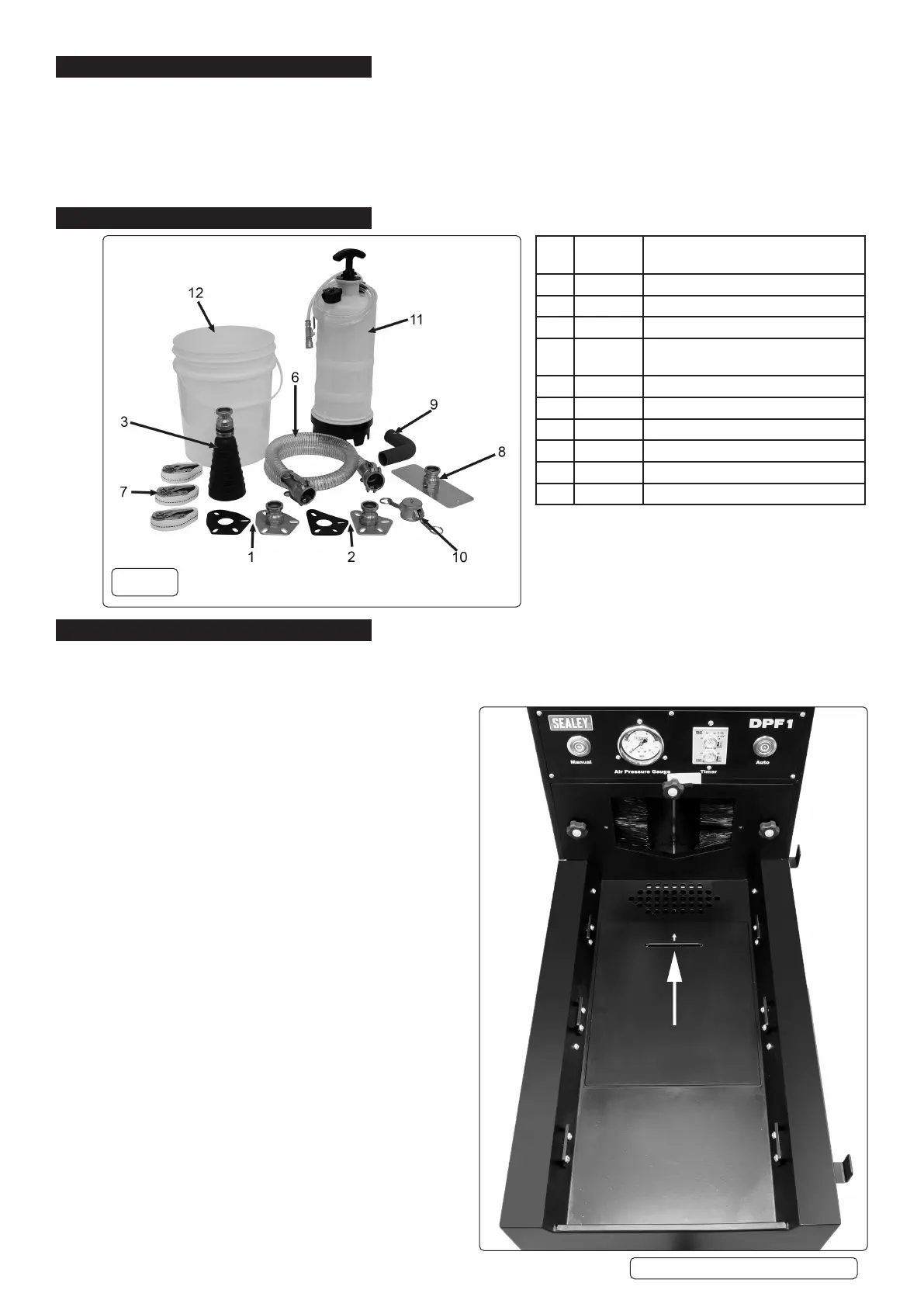
4. CONTENTS
5. OPERATION
5.1. DPF PREPARATION
5.1.1. Select a suitable adaptor and gasket (g.1-1, g1-2, g1-3) for the DPF. Ensure a good t to the DPF to avoid spillage. Close o the
adaptor using the Soaking Cap (g.1.10). Block o any DPF pressure tappings.
5.1.2. Pour Ultra Clean detergent into inverted DPF and ll to the top
face of the internal structure.
5.1.3. Leave the DPF in a vertical position for minimum of 30 minutes
and regularly agitate it in order to ensure full coverage of solution
within the DPF and to begin the cleaning eect.
5.1.4. Empty the contents into a suitable container after soaking the
DPF for a suitable period.
5.2. OPERATIONPREPARATION(g.4)
5.2.1. Ensure that the unit is not connected to the power supply.
5.2.2. Lay drained DPF onto machine bed ensuring the DPF outlet is
beyond the brushes at the machine entrance.
NOTE: If the outlet of the DPF does not t fully into the aperture
on the machine, remove the cover by using the three
thumbscrews on the face plate and fully engage the DPF into
the exposed space.
NOTE: Some PDFs are not designed as ‘straight-through’ e.g.
they may be ‘L’ or even ‘Z’ shaped. In certain circumstances it is
advised to remove the aperture entrance cover, t the discharge
adaptor (g.1.8) in place of the cover and attach the clear pipe
(g.1.6) between the adaptor and the DPF.
5.2.3. Strap DPF rmly to the machine bed using the supplied ratchet
bars (g.1.7).
5.2.4. Remove Soaking Cap from DPF and connect air supply to the
adaptor tted to the unit.
5.2.5. Fill the water pressure container (g1.11) with the appropriate
amount of water that DOES NOT exceed the capacity of the
waster bucket.
5.2.6. Connect the water supply tting to the inlet of the air line tting
(g.3). Ensure that the water outlet valve is closed at this stage.
NOTE: Ensure cover plate is placed with the arrow facing
themachineentrance(seediagramright).
Original Language Version
© Jack Sealey Limited
g.1
Item
No.
Part No. Description
1 DPF01.01 Adaptor 1 + Gasket
2 DPF01.02 Adaptor 2 + Gasket
3 DPF01.03 Adaptor 3 (Small Vehicle)
6 DPF01.06 DCS Clear Hydraulic Pipe (1-1/4”F to
1-1/4”F) 1.5m
7 DPF01.07 Mini Ratchet Bar (25mm x 1.5m)
8 DPF01.08 Discharge Adaptor (Small)
9 DPF01.09 Waste Water Hose (38mm)
10 DPF01.10 Soaking Cap (1-1/4)
11 DPF01.12 Water Pressure Container
12 DPF01.13 Waste Water Bucket
DPF1 Issue 2 (5) 23/09/20
 Loading...