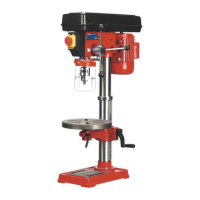
fig. 2
fig. 3
fig. 4
fig. 4
fig. 5
6. OPERATION
WARNING! Ensure the drill is unplugged from the mains power supply before commencing.
6.1. Install drill bit
6.1.1. Insert drill bit into chuck jaws to 1" (25mm) deep (avoid inserting small bits too far) and centre bit in chuck before tightening.
6.2. Adjusting the table
6.2.1. To adjust table up or down, loosen the clamp bolt (fig.2.B) then turn the bracket handle (fig.2.A).
6.2.2. To adjust table tilt, loosen the work table bolt (fig.2.C), remove locking pin (below bolt) and adjust to the desired angle using the
angle scale, then retighten. When returning table to horizontal replace locking pin.
6.2.3. To turn the table around the column, loosen the rack collar slightly, then loosen the clamp bolt (fig.2.B).
Turn the table to the desired position then secure the bolt and the rack collar.
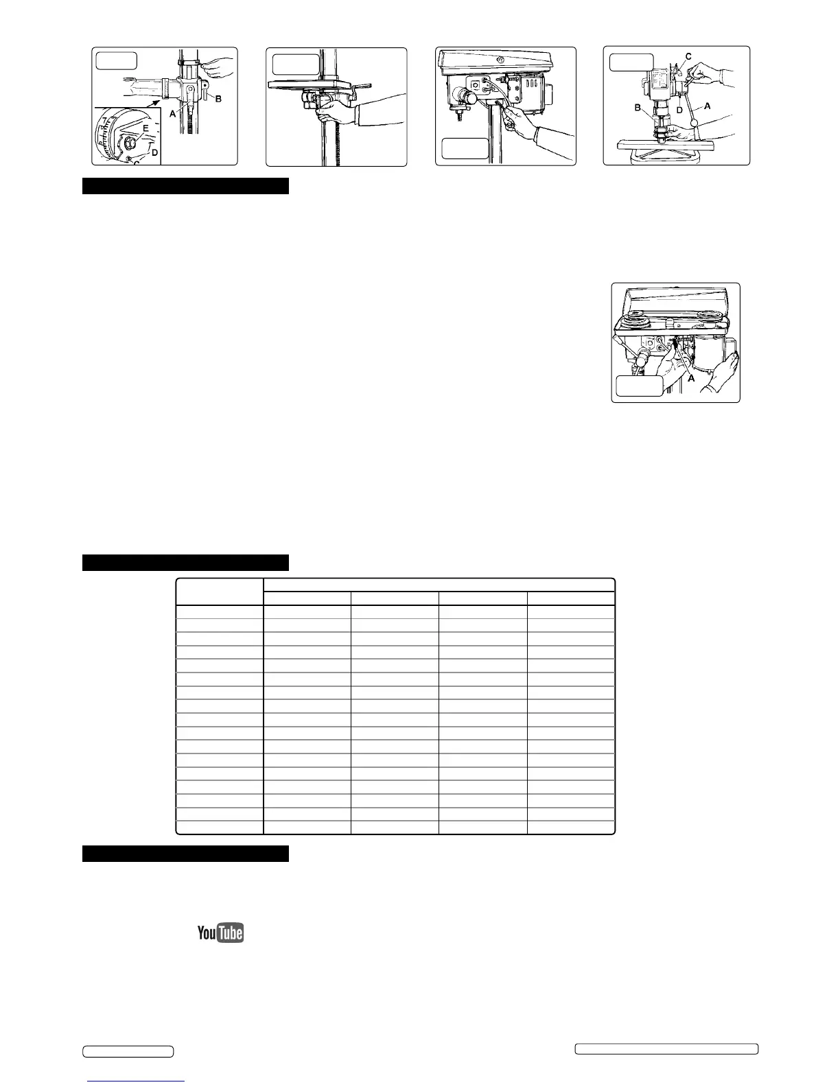
6.3. Adjusting the speed
NOTE: the belt cover is tted with a micro-switch to prevent drill operation with the cover open.
6.3.1. Open the pulley case and loosen the belt tension lock screws (fig.6.A) - one either side of head.
6.3.2. Choose the speed for drilling operation (see drill speed chart - Section 7) and move the belts to the
correct position for that speed, as shown on the chart inside the pulley cover.
6.4. Belt tension
6.4.1. With the belt tension lock screws (fig.6.A) loose and using hand pressure on the adjusting handle
(fig.5.C), set tension so that belt deflection is no more than 1/2" (13mm). Tighten lock screws.
6.5. Positioning the workpiece
6.5.1. Use a piece of wood to rest the workpiece on. The drill bit may break through the workpiece and damage the table otherwise.
The wood should rest on the table so that one end of it is against the left side of the column, to prevent it spinning when the drill
bit breaks through the workpiece.
6.5.2. For small workpieces that cannot be clamped to the table, use a drill vice (not included). Vice must be clamped or bolted to table.
6.6. Setting the drill depth
6.6.1. Use the scale on the side of the drill head near the drill handle.
6.6.2. Loosen locking screw (fig.5.D) and set the scale to the depth desired. Tighten locking screw.
6.6.3. When ready to drill, simply pull the feed handle. The drill will stop at the set depth.
fig. 6
7. DRILL SPEEDS
Drill Speed (rpm)
Drill Dia. (mm)
Steel Cast Iron Iron Alum. & Copper
3 1820 2580 2580 2580
4 1350 1820 1820 2580
5 1290 1350 1350 2580
6 970 1290 1290 2580
7 830 970 970 2580
8 830 970 970 2580
9 500 970 830 1820
10 500 830 830 1820
11 500 830 830 1820
12 420 830 500 1820
13 420 500 500 1350
14 420 500 500 1350
16 320 500 500 1290
18 320 420 420 1290
20 280 320 320 970
22 210 320 280 970
25 120 280 210 830
8. MAINTENANCE
WARNING! Disconnect drill from mains power before changing accessories, servicing or performing any maintenance.
8.1. Clean the tool after each use. A coat of maintenance spray applied to the table and column will help to keep the surfaces clean.
8.2. Blow out any dust that may have accumulated in the motor.
8.3. Periodically lubricate the table elevation rack/gear/worm mechanism and the spindle sleeve exterior.
8.4. Belt changing Please note that an instructional video for this product is available to view on our YouTube channel.
8.4.1. Isolate the drill from the power supply.
8.4.2. Remove the belt tension as in section 6.4.
8.4.3. Remove the belt(s) and replace with another of the same specification.
8.4.4. Re-tension the belts as in section 6.4.
8.4.5. Close and secure the pulley case.
Original Language Version
© Jack Sealey Limited
GDM92B,GDM140F Issue: 7 (SP) - 26/04/18
 Loading...