3.1. Remove compressor from packaging and inspect. If anything is found to be missing or damaged contact your supplier.
3.2. Save the packing material for future transportation of the compressor. We recommend that you store the packing
in a safe location, at least for the period of the guarantee. Then, if necessary
, it will be easier to send the
compressor to the service centre.
3.3. Confirm that the voltage shown on compressor data plate corresponds with the supply voltage.
3.4. The compressor should be operated on a flat surface, or one that does not exceed 15
O
either transversely
or longitudinally (fig.2), and should be in a position that allows good air circulation around the unit.
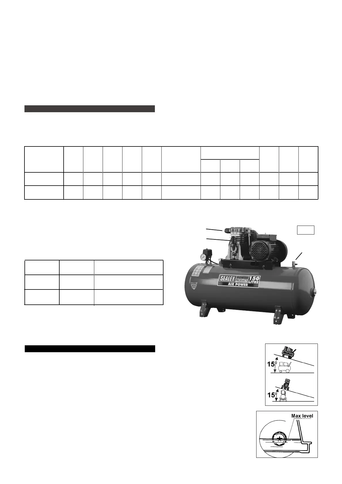
3.5. Confirm that the air filter (fig.1.A) is fitted to the inlet port of the cylinder head and that the breather (fig.1.B)
is fitted to oil filler port.
3.6. Confirm that the oil level is at the maximum mark on the sight glass (fig.3).
2. INTRODUCTION & SPECIFICATIONS
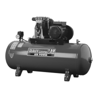
The SA1015/3 and SA1020/3 Compressors have twin cylinder pumps belt driven by 230V 1ph motors and are capable of supplying air at up to
10 bar. In addition to pneumatic tools, the compressors are suitable for running accessories for blowing, washing, spraying and tyre inflation.
SA1015/3 & SA1020/3 - 1069 - (2) - 050601
3. PREPARATION
Free Air Delivery
(cfm)
Model
Max
Motor
Output
(hp)
Voltage/
Phase
Current
(A)
Pump
Type
Pump
Speed
(rpm)
Piston
Displacement
(cfm)
At
2.5 Bar*
Max.
At
6.0 Bar*
Tank
Capacity
(l)
Max.
Pressure
(psi/bar)
Noise
Level
(dB.A)
SA1015/3
SA1020/3
3
3
230/1
230/1
13
13
K9
K9
1800
1800
14
14
10.2
10.2
10.6
10.6
9.9
9.9
150
200
145/10
145/10
79
79
2.1. Specifications
2.2. Weights & Dimensions
fig. 3
fig. 1
Model
Weight
(kg)
Dimensions
Length x Width x Height (mm)
SA1015/3
SA1020/3
79
91
1280 x 420 x 830
1420 x 420 x 1000
fig. 2
All performance figures are ± 5%
7 DO NOT cover the compressor or restrict air flow around the machine whilst operating.
s DANGER! DO NOT direct the air hose towards people or animals.
7 DO NOT operate the compressor without an inlet air filter (see fig.1.A).
7 DO NOT allow anyone to operate the compressor unless they have received full instructions.
p WARNING! The air tank is a pressure vessel and the following safety measures apply:
DO NOT tamper with the safety valve, DO NOT modify or alter the tank in any way and DO NOT strap anything to the tank.
DO NOT subject the tank to impact, vibration or to heat and DO NOT allow contact with abrasives or corrosives.
DO drain condensation from tank daily, inspect inside walls for corrosion every three months and have a detailed tank inspection
carried out annually.
The tank shell must not fall below the certified thickness at any point.
p WARNING! If an electrical fuse blows, ensure it is replaced with an identical fuse type and rating (See para. 1.1.11).
3 When not in use, store the compressor in a safe, dry, childproof location.
* Note: 2.5 bar is recommended pressure setting for spraying.
6.0 bar is recommended pressure setting for air tools.
A
B
C
 Loading...