4.3.2. Carefully position display panel into position, making sure wiring is
not twisted.
4.3.3. Insert the three screws through
the back panel and into the aligned
display panel.
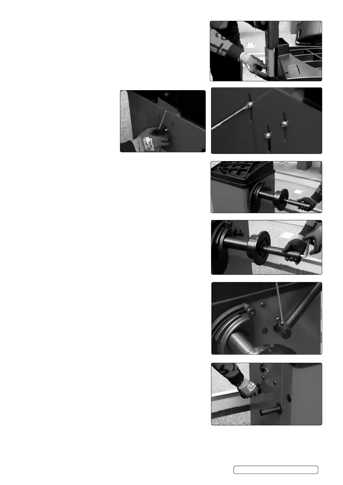
4.3.3.1. Install the threaded shaft.
4.3.4. Tighten threaded shaft with Hex key
4.3.5. Install wheel guard with supplied screws and tighten with Hex key.
4.3.6. Install side handles.
WB10 | Issue 1 05/02/18
Original Language Version
© Jack Sealey Limited