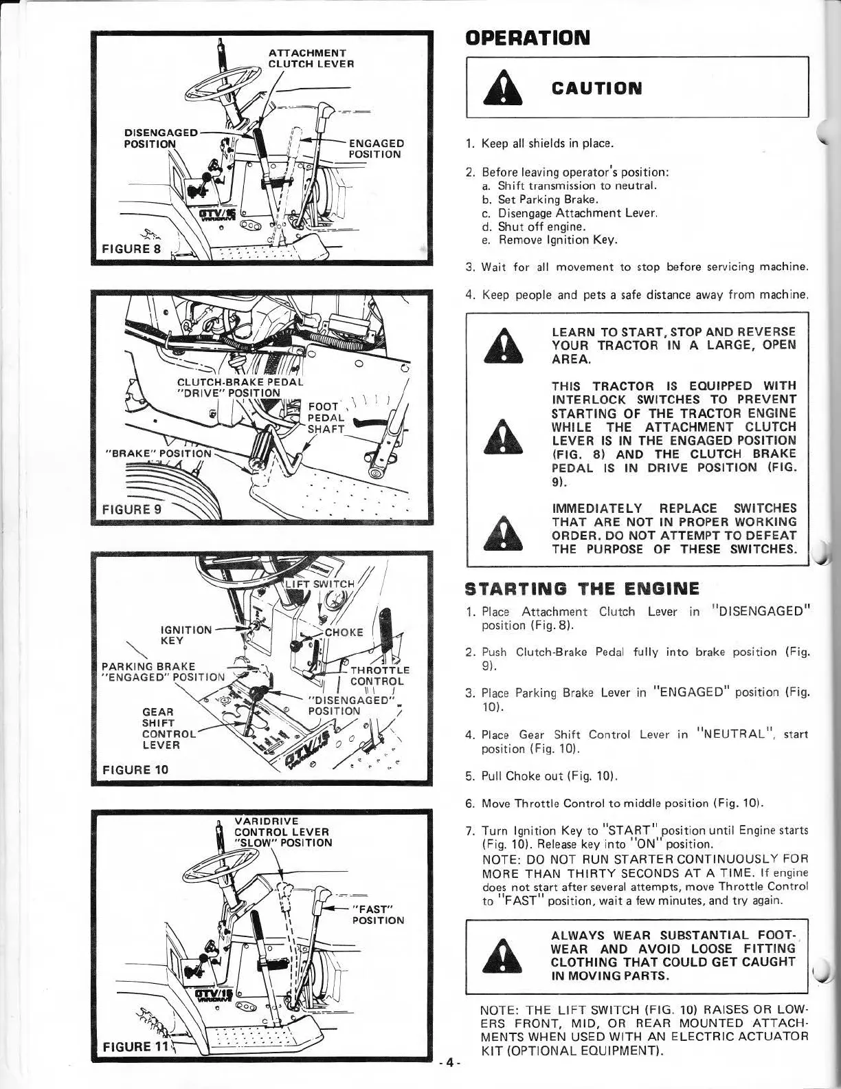
ATTACHMENT
CLUTCH
LEVER
--h_
FIGURE 8
IGNITION
_.....,;::.QJ""ol
KEY
PARKING
BRAKE
"ENGAGED"
POSITION
GEAR
SHIFT
CON
TROL
LEVER
FIGURE 10
VARIDRIVE
CONTROL
LEVER
"SLOW"
POSITION
~
~
--~--------
"FAST"
POSITION
OPERATION
[A
CAUTION
1.
Keep
all shields in place.
2.
Before leaving operator's position:
a.
Shift
transmission to neutral.
b.
Set
Park
ing Brake.
c.
Disengage
Attachment
Lever.
d. Shut
off
engine.
e.
Remove
Ignition Key.
3.
Wa
it
fo
r all movement to stop before
serv
icing machine.
4.
Keep
pe
ople
and
pets a
safe
distance
away
from machine.
LEARN
TO START,
STOP
AND
REVERSE
YOUR TRACTOR IN
A LARGE, OPEN
AREA.
THIS TRACTOR
IS
EQUIPPED WITH
INTERLOCK SWITCHES TO
PREVENT
STARTING
OF
THE TRACTOR ENGINE
WHILE
THE ATTACHMENT CLUTCH
LEVER
IS
IN
THE ENGAGED POSITION
(FIG.
8)
AND
THE CLUTCH BRAKE
PEDAL
IS
IN
DRIVE
POSITION (FIG.
9).
IMMEDIATELY
REPLACE SWITCHES
THAT
ARE NOT
IN
PROPER WORKING
ORDER. DO
NOT
ATTEMPT TO
DEFEAT
I
}'
THE
PURPOSE
OF THESE SWITCHES.
~
~
STARTING
THE
ENGINE
1.
P
lace
Attachm
ent
Clutch Lever in "DISENGAGE
D"
position (Fig. 8).
2.
Push
Clutch-Brake
Pedal
fully
into
brake position (Fig.
9).
3.
Place
Parking Brake Lever in
"ENGAG
ED"
position (Fig.
10).
4.
Place
Gear
Shift Control
Lev
er
in
"NEUTRAL",
start
position (Fig.
10).
5. Pull Choke
out
(Fig. 10).
6.
Move
Throttle Control
to
middle position (Fig. 10).
7.
Turn Igni
tio
n Key to
"START"
position
until
Engine starts
(Fig.
10).
Release
key
into
"ON"
position.
NOTE:
DO
NOT RUN STARTER CONTINUOUSLY FOR
MORE
THAN
THIRTY
SECONDS
AT
A TIME.
If
engine
does
not start after
several
attempts, move Throttle Control
to
"FAST"
position, wait a few minutes,
and
try
again.
ALWAYS WEAR
SUBSTANTIAL
FOOT-
WEAR
AND
AVOID
LOOSE
FITTING
CLOTHING
THAT
COULD GET CAUGHT
IN
MOVING
PARTS.
\..,l
NOTE: THE
LIFT
SWITCH (FIG. 10) RAISES
OR
LOW-
ER
S FRONT,
MID,
OR
REAR MOUNTED
ATTACH-
MENTS WHEN USED WITH
AN
ELECTRIC ACTUATOR
KIT
(OPTIONAL EQUIPMENT).
another free manual from www.searstractormanuals.com