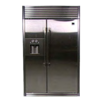
Do you have a question about the Sears Kenmore PRO 401.40483800 and is the answer not in the manual?
| Brand | Sears |
|---|---|
| Model | Kenmore PRO 401.40483800 |
| Category | Refrigerator |
| Language | English |
Read these instructions completely and carefully.
Essential safety guidelines for operating the refrigerator to prevent injury or damage.
Critical warnings and guidelines related to the refrigerator's electrical components and usage.
Warnings against improper use of extension cords and adapter plugs.
Guidelines for safely disposing of the refrigerator, preventing child entrapment.
Instructions and checklist for ensuring the refrigerator is properly grounded for safety.
Details required installation space, ventilation, and wall clearances for proper operation.
Key product specifications including capacity, dimensions, weight, and power ratings.
Detailed specifications for major components like compressor, evaporator, and sensors.
List and specifications of various electrical parts used in the refrigerator.
Detailed measurements and diagrams of the refrigerator's physical size and door opening clearances.
Visual representation of the refrigerant flow and its path through the system.
Diagrams illustrating how cold air is circulated within the freezer and refrigerator compartments.
Explanation of the fan motor's delay function and its relation to ambient temperature.
Detailed operation, testing procedures, and error handling for the ice maker.
Explanation of the defrost cycle, its dependencies, and related temperature comparisons.
Details on the button touch sound and door-open alarm features and their behavior.
How the unit restores operating conditions after a power interruption or initialization.
Functionality and interpretation of the load status display via LEDs and button inputs.
Procedures for initiating and performing forced operation and forced defrost tests.
How to initiate and interpret self-diagnosis for errors during power-on and normal operation.
Illustrated overview of internal parts and corresponding page numbers for disassembly.
Step-by-step instructions for removing and replacing dispenser-related components.
Procedures for removing and replacing door handles, panels, and bulbs.
Instructions for removing freezer and fridge doors, chassis, and other major parts.
Steps for removing and reinstalling internal storage bins, drawers, and shelves.
Procedures for disassembling the ice maker and the freezer compartment evaporator.
Instructions for removing the freezer compartment evaporator, fan motor, and related parts.
Steps for replacing interior lamps and accessing defrost heaters/sensors.
Procedures for removing ducts, rails, and temperature control drawer components.
Instructions for accessing and replacing compartment sensors and fan assemblies.
Steps for disassembling machine compartment parts, gas springs, and switches.
Procedures for removing the transformer and accessing the PCB housing.
Instructions for accessing the condenser, fan motor, and power switch components.
Procedures for handling water pipes, valves, and the power cord.
Diagram showing the layout and numbering of case output terminals for diagnosis.
High-level overview of the refrigerator's control system and component interactions.
Overall wiring schematic illustrating connections between major components and terminal blocks.