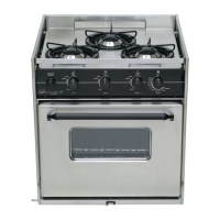
GIMBALED MODELS – 2 & 3 BURNERS
1. It is important that the following minimum clearances from combustible materials be adhered to when
installing your gimbaled range. .
2 BURNER MODEL:
• Side – 7” minimum as measured from the center line of the closest burner head.
• Rear - 9” minimum as measured from the center line of the closest burner head.
• Top – 24” minimum to overhead cabinets, shelves or any other combustible material.
3 BURNER MODEL:
• Side – 5.1/2” minimum as measured from the center line of the closest burner head.
• Rear - 7” minimum as measured from the center line of the closest burner head.
• Top – 24” minimum to overhead cabinets, shelves or any other combustible material.
2. Make a cardboard template the same size as the side view of the range. Punch a hole at the gimbal
location the size of the gimbal, and swing the appliance template in the appliance cut-out location in the
boat on your finger. By allowing a swing approximately 15° to 20° before interference with the hull or
boat structure, the gimbal point can be located. Mark the point. Make certain that after the gimbal point
is determined that the installation matches or exceeds the minimum clearance in paragraph #1. It is
important that the oven vent be completely clear so that burned gases can discharge to the open air. If
this vent is blocked, poisonous gas could be produced. .
3. Locate the companion pieces to the gimbals and install the appliance.
4. For safety, Seaward Products gimbaled appliances are designed with a sliding bolt type lock. The
sliding bolt should lock into an adjacent cabinet or bulkhead to prevent the appliance from swinging in
rough weather.
CAUTION:
The appliance center of gravity will also shift from the gimbal location when pots are
not balanced on the appliance or when the appliance door is open.
5. Connect the LPG fuel supply hose fitting to the brass fitting on the appliance manifold and on the
regulation system. Wrench tighten the fitting to the connection on the appliance. DO NOT use pipe
dope or Teflon tape.
6. Check all gas connections for possible leaks. Turn the valves on your range to their “OFF” position.
Open valve on gas supply tank. Using a strong soap and water solution,( ½ liquid soap and ½ water),
check each gas connection one at a time by brushing the soap and water solution over the connection.
Presence of bubbles will indicate a leak. Tighten fitting and recheck for leaks. DO NOT USE OPEN
FLAME FOR CHECKING GAS LEAKS.
7. Place burner grates in place with the clips provided. An instruction sheet is provided for the grate clips.
These grate clips will hold the grate in place while under way.
8. Light the burners for testing.
9. The appliance is now ready for use. Sometimes the burners will not ignite immediately and seem to
“blow” slightly when they do ignite. This is usually due to the presence of air in the gas lines, which will
clear itself within seconds.
 Loading...