F LED signaling
Refer to the following table. The Power LED is Green when power is supplied.
State (All models) STATUS CONNECT
Booting Steady Red Blink -
GateManager Connecting
or Disconnected
2 Red Blink -
- Remote Management is disabled via INPUT1
or SiteManager GUI
- SiteManager in SMS Wakeup mode
- long pause + 2
Green Blink
GateManager Connected On Green -
- UPLINK is physically disconnected, or
- GateManager configuration is missing in
the SiteManager, or
- No route to GateManager host due to its
address being configured as DNS name,
and a DNS server is not configured or is not
reachable/working.
On Red -
LinkManager Connected - On Green
State (model xx49 only) UPLINK2
- No WiFi SSID configured
- SSID configured but no WiFi Key configured
- SSID and WiFi Key configured, but no ac-
cess point found matching the SSID.
Off
WiFi SSID Found but not connected yet. Pos-
sible WiFi Key error.
2 Green Blink
WiFi connected successfully. On Green
State (xx39 models only) UPLINK2
No SIM card detected Off
Wrong or missing SIM Pin code 3 Green Blink
SIM PIN code OK, but no connection.
(Trouble shoot in SiteManager GUI)
2 Green Blink
GPRS connected (slow connection) On Green + 1 Green Blink
3G or 4G connected (fast connection) On Green
SiteManager is in SMS Wakeup mode long pause + 2 Green Blink
Note that it may take some time for the Status LED to reect a new state. For instance a GM
Disconnect may take up to 4 minutes to be reected, depending on the Keep-alive Interval set-
ting on the GateManager.
G USB ports (USB cable is not included with the product)
The USB port can be used for attaching selected USB equipped PLCs and for connecting a
noptional USB broadband adapter to use as Internet connection (see details below)
Note: The USB port limits the power drain for peripheral devices to 500mA per USB connector
in compliance with the USB 2.0 standard.
H IO Ports
Digtial Input port 1 and 2: In “OFF” (inactive) state at 2.34 V or above, and in the “ON” (ac-
tive) state at 0.16 V or below. The behavior for input voltages between 0.16 V and 2.34 V is
undened.
There is an internal 10 kohms pull-up resistor to 3.3 V, so an unconnected input port is in the
“OFF” state. Input port 1 is by default assigned to toggle GateManager Access. By connecting a
simple on/o switch you can control when remote service should be allowed.
Relay Output 1: Output1 is a “dual pin” port where both pins are isolated when OFF and short-
circuited when ON. Output port 1 is by default congured to go active when a LinkManager is
connected, and can be used to turn on a lamp that noties the users that the device is being
serviced.
Maximum sink current is 0.5 A. Maximum Voltage is 24V
Digital Output 2: Output2 is a “single pin” port, which is pulled towards GND when ON, and
is high-impedance when OFF. The port is an “open drain” kind, which means that (just like
a switch) no voltage is output by the port itself, but must be supplied either from an external
source (max 24 V) or from the Vout (5V) pin. In the “OFF” (inactive) state, the impedance is min
24 Mohms; in the “ON” (active) state, the impedance is max 0.5 ohms. Maximum sink current
is 0.2 A.
Refer to the guide “Working with IO ports” for application scenarios.
I Serial ports (Serial cables are not included with the product)
SiteManager is equipped with a RS232 Serial port with full ow control support. The pinout of
the DB9 connector corresponds to the standard Serial COM port of a PC. You should be able to
use an ordinary NUL-modem cable for most equipment.
- For Omron PLCs use the cable XM2S-09.
- For Siemens MPI- or PPI connection use either a RS232-to-MPI adapter,
a USB-to-MPI adapter or an Ethernet-to-MPI/PPI adapter (Secomea p/n 26940)
- For other PLCs refer to the documentaiton for the PLC for information about special Serial
pinout.
J Internet access via broadband modem (UPLINK2)
Note: On xx39 models a broadband modem is integrated. On xx29 models you must
install an external 4G/3G/GPRS USB modem. The SiteManager includes a large number
of USB modem drivers, but not all may work. Refer to the Secomea web site for a USB
modem compatibility list.
The broadband modem connection is referred to as UPLINK2. The SiteManager will as default
always attempt to use the Ethernet connection (UPLINK1), and only use UPLINK2 if the Internet
connection is lost on UPLINK1. Once a connection is established on UPLINK2, switching to
UPLINK1 will only be attempted at next reboot, or if the Internet connection on UPLINK2 is lost.
I the modem is using a SIM PIN code you should enter the PIN code in the System > UPLINK2
menu of the SiteManager. The SiteManager will automatically detect the APN (Access Point
Name) from an internal table, but can also be manually entered via the SiteManager GUI.
If your modem or SIM card does not have a PIN Code, you do not have to make any further con-
guration of UPLINK2 in the SiteManager (The PIN Code can be removed from a SIM card by
inserting it into a standard mobile phone, and use the remove SIM card function of the phone).
In order to reduce data trac, you can congure UPLINK2 to let the broadband connection enter
sleep-mode if idle. The connection will be reestablished when sending an SMS to the phone
number on the SIM card.
Note that when using a USB WiFi adapter as explained in the following, broadband uplink is
disabled.
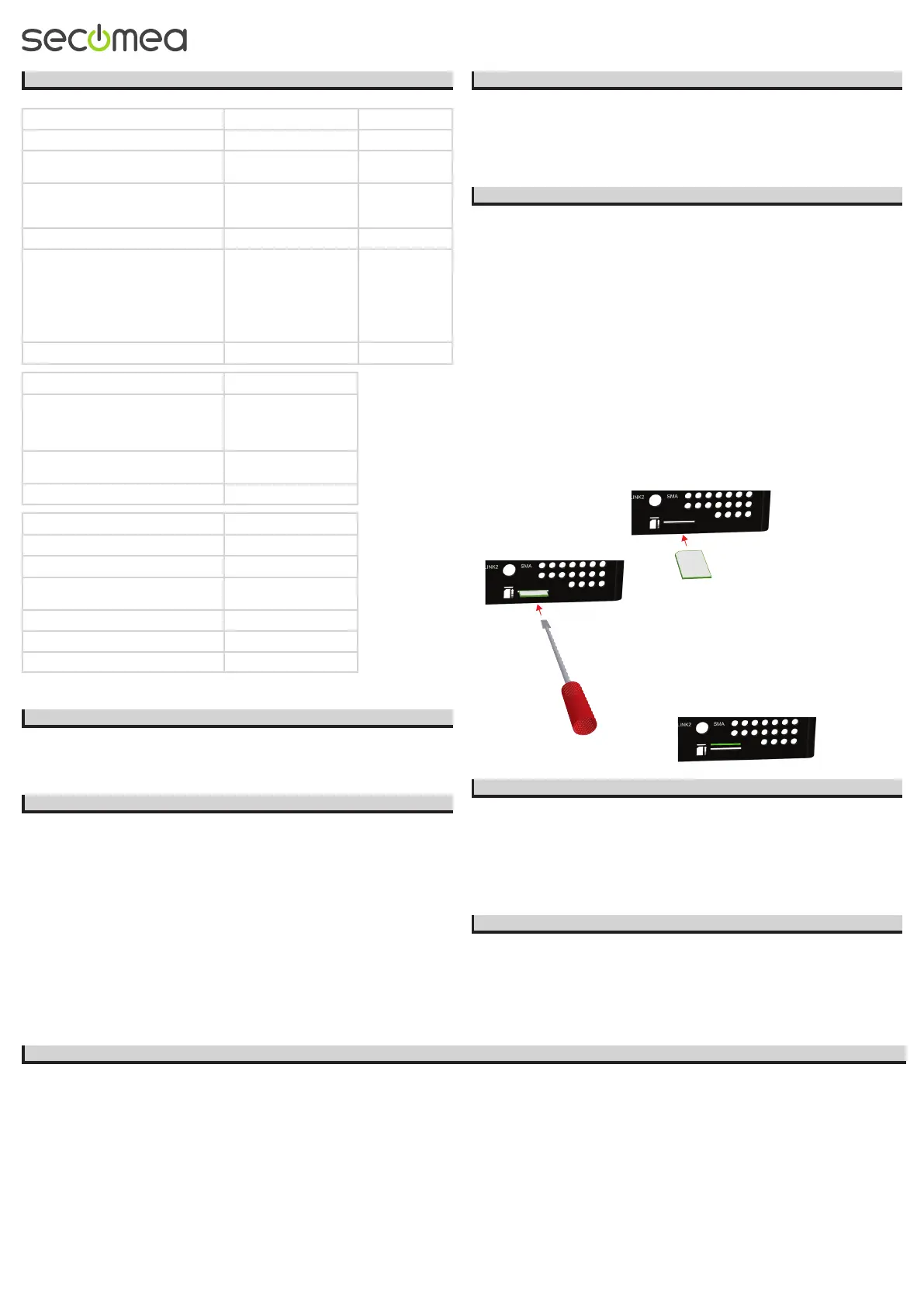
SIM insertion (xx39 models):
Note models 1139 and 3339 requires a Standard SIM (15 x 25mm) while model 3539 requires a
Micro SIM (12 x 15mm).
Slide the SIM card into the slot.
Use a sharp object, such as a
screwdriver, to push the SIM card
further into the slot (approx 2 mm),
until you hear the click of the
spring lock.
The SIM card is properly inserted when it is
level with the SiteManager cabinet.
K Internet access via WiFi (UPLINK2)
On xx49 models a WiFi client module is integrated. On other models WiFi client mode
can be achieved by inserting a Secomea USB WiFi adapter (e.g. p/n 27250).
The connection is referred to as UPLINK2. When enabling the WiFi client, the SiteManager
will be by default attempt to connect with the SSID “sitemanager” and the MAC address of the
SiteManager as WiFi Key. A specic SSID and WiFi Key can be congured in the System >
UPLINK2 menu.
Note that connecting the USB WiFi adapter will disable any integrated wireless module
used for UPLINK2.
L WiFi Access Point (AP) support via external USB WiFi adapter
3549 models can operate as a WiFi access point with the integrated WiFi, and 1149 and
3349 models can operate as a WiFi Access Point using a Secomea USB WiFi adapter (e.g.
p/n 27250).
The SSID to be broadcasted in AP mode and the WiFi Key can be congured in the System >
DEV1 menu.
Note that connecting the USB WiFi adapter to 1149 and 3349 models will disable the
integrated WiFi module used for UPLINK2.
M Regulation Notices
Product compliancy: • CE • CAN ICES-3 (A)/NMB-3(A) • FCC 47 cfr part 15 * • UL Listed (le #E358541, ITE 4ZP8) • IEC CB certied (DK-30193-A2-UL) • RCM Compliant • Japan Tele MIC (007-D160018007) (xx49 models)
* NOTE: This equipment has been tested and found to comply with the limits for a Class A digital device, pursuant to Part 15 of the FCC Rules. These limits are designed to provide reasonable protection against harmful interference when the equipment is
operated in a commercial environment. This equipment generates, uses, and can radiate radio frequency energy, and if it is not installed and used in accordance with the instruction manual, it may cause harmful interference to radio communications. Opera-
tion of this equipment in a residential area is likely to cause harmful interference, in which case the user will be required to correct the interference at his own expense.. Operation is subject to the following conditions:
1. This device may not cause harmful interference.
2. his device must accept any interference received, including interference that may cause undesired operation.
Specic to the integrated WiFi module (models 1149 and 3349 only)
1. The module supports IEEE 802.11 b/g/n radio in the 2.4 GHz band, with a maximum output power of +15dBm for IEEE 802.11g/n and +17dBm for IEEE 802.11b
2. The module is listed under FCC Certication ID: QOQWF111 and IC: 5123A-BGTWF111. To fully comply to FCC/IC the maximum gain of a connected antenna must not exceed 2.0 dBi
Specic to the integrated WiFi module (model 3549 only)
1. The module supports IEEE 802.11 b/g/n/ac radio in the 2.4 GHz and 5GHz bands, with a maximum output power of +16dBm for IEEE 802.11g/n, +18dBm for IEEE 802.11b and 10dBm for IEEE 802.11ac
2. The module is listed under FCC Certication ID: TLZ-CM389NF and IC: 6100A-CM389NF. To fully comply to FCC/IC the maximum gain of a connected antenna must not exceed 2.0 dBi
Specic to the integrated broadband module (4G/US versions of models 1139, 3339 and 3539 only)
1. The module is PTCRB and FCC approved. To fully comply to FCC/IC the following conditions must be met: a) At least 20 cm separation distance between the antenna and the user’s body must be maintained at all times. b) The maximum gain of
a connected antenna including cable loss in a mobile-only exposure condition must not exceed 3.5 dBi in the cellular band.
第十二條 經型式認證合格之低功率射頻電機,非經許可,公司、商號或使用者均不得擅自變更頻率、加大功率或變更原設計之特性及功能。 第十四條 低功率射頻電機之使用不得影響飛航安全及干擾合法通信;經發現有干擾現象時,應立即停用,並改善至無干
擾時方得繼續使用。 前項合法通信,指依電信法規定作業之無線電通信。 低功率射頻電機須忍受合法通信或工業、科學及醫療用電波輻射性電機設備之干擾。
 Loading...