1/3 DES.I.101.T1.02 / 520N1301 June 2021
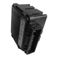
Fig. 1
ENGLISH
The electronic unit is a dual voltage device. This
means that the same unit can be used in 12V
or 24V power supply systems. Maximum volt-
age is 17V for a 12V system and 34V for a 24V
power supply system. Max. ambient temperature
is 55°C. The electronic unit has a built-in thermal
protection which is actuated and stops compres-
sor operation if the electronic unit temperature
gets too high (100°C/212°F on the PCB). It can
be connected to a PC through the Secop One
Wire/LIN Gateway communication interface on
the terminal D/I and C (Fig. 1). Communication
gateway modules incl. communication cables
can be ordered at Secop.
The PC interface allows you to create dierent
settings and reads out several measurements by
using the software tool TOOL4COOL® supplied
by Secop.
Installation (Fig. 3)
Mount the electronic unit directly on the compres-
sor plug and x it with screws.
Power supply (Fig. 1)
The electronic unit must always be connected
directly to the battery poles. Connect the plus to
+ and the minus to –, otherwise the electronic
unit will not work. The electronic unit is protected
against reverse battery connection. For protec-
tion during installation, a fuse must be mounted
in the + cable as close to the battery as possible.
A 15A fuse for 12V and a 15A fuse for 24V
circuits are recommended.
If a main switch is used, it should be rated to a
current of min. 20A.
The wire dimensions in Fig. 4 must be observed.
Avoid extra junctions in the power supply system
to prevent voltage drop from aecting the battery
protection setting.
Battery protection (Fig. 2)
The compressor stops and restarts again accord-
ing to the designated voltage limits measured on
the + and – terminals of the electronic unit. The
standard settings for 12V and 24V power supply
systems are shown in Fig. 2. (PC option)
Other settings are (Fig. 5) optional if a connec-
tion which includes a resistor (R1) is established
between terminals C and P (non PC option).
Thermostat (Fig. 1)
The thermostat is connected between the termi-
nals C and T. Either a NTC (electrical thermostat)
or a mechanical thermostat can be connected.
Three dierent thermostat modes can be chosen
in the software - Auto (both NTC and mechanical),
NTC or Mechanical. Standard setting is Auto. In
case of using a NTC the set point in the range
between -40ºC and 40ºC is set with the software
and the temperature can also be seen by using
the interface. When using the Auto setting in the
software it is not possible to obtain NTC failures,
so it is recommended to set the thermostat mode
to NTC when using a NTC.
Setpoint selection (Fig. 6)
In order to utilize the nally intergrated tempera-
ture control. You can connect a 10kΩ potentiom-
eter between S and C (R2). Via this resistor a
temperature setpoint between -20°C and 10°C
can be selected. The compressor will stop when
the set point is measured on the NTC and re-
start at set point +1kΩ or 3K (Kelvin) (non PC
option).
Speed selection (Fig. 5)
The compressor will run with a xed speed of
4,000 rpm when the thermostat is switched on.
Other xed compressor speeds and start speeds
in the range between 2,000 and 4,000 rpm can
be obtained when changing the speed settings
in the software (PC option) or with the resistor
(non PC option).
A start delay in the range from 0-240 sec. (factory
setting 4 sec.) after thermostat cut-in can also be
chosen. By default the compressor will start with
a speed of 2,500 rpm for the rst 30 seconds.
Fan (Fig. 1)
A fan can be connected between the terminals
+(F) and F. Connect the plus to +(F) and the mi-
nus to F. Since the output voltage between the
terminals +(F) and F is always regulated to 12V,
a 12V fan must be used for both 12V and 24V
power supply systems.
The fan output can supply a continuous power
of 6W
avg. A higher current draw is allowed for 2
seconds during start.
Fan settings can be adjusted via TOOL4COOL®.
The factory default setting in the controller is:
Detect missing fan - Disabled.
The unit has to be restarted when these settings
have been changed. If a fan is used without ad-
apting the TOOL4COOL® settings, the fan will
run but no error signal will be sent in case of fan
failure. It is also possible to set a start delay on
the fan in the range from 0 – 240 sec. but only if
a fan is connected and not running.
Factory default setting for a fan is 0 seconds.
Fan speed can be adjusted through the interface
from 40 – 100%.
Error handling (Fig. 7)
If the electronic unit records an operational error,
the error can be read out in the software
(PC op-
tion). Error codes are dened as shown in Fig. 7.
A 10mA light emitting diode (LED) can alterna-
tively be connected between the terminals D/I
and +. In case the electronic unit records an
operational error, the diode will ash a number of
times. The number of ashes depends on what
kind of operational error was recorded. Each
ash will last ¼ second. After the actual number
of ashes there will be a delay with no ashes,
so that the sequence for each error recording is
repeated every 4 seconds
(non PC option)
.
101N2130
IN
12/24V
FAN OUT
D/I
C
T
C
P
S
F
F
+
-
-
+
One Wire LIN Gateway
USB
USB C
U+*
D/I
C
U
C
1
2
LIN
BAT
105N9518 – V01.00
www.secop.com
Made in Germany
* Don‘t connect when
using D/I on BD-Products
Secop LIN/One-Wire
Gateway
Code no.:105N9516
Comm.
PC option (TOOL4COOL®)
Gateway connected to ,, andU D/I C
BAT
8910-2
Main switch
Fuse
Power supply
NTC resistor
–t°
mech. Thermostat
Fan
-
+
R1
R2
+
-
LED
R1 = speed/battery protection
R2 = setpoint
non PC option (resistors)
non PC option
LED connected to
and+ D/I
Spade connectors
6.3 mm | 1/4 in.
Fig. 7
Operational errors (PC or non PC option)
Error
code
or LED
ashes
Error type
Can be read out in the software
TOOL4COOL®
6
Thermostat failure
(If the NTC thermistor is short-circuit or has
no connection, the electronic unit will enter
manual mode).
5
Thermal cut-out of electronic unit
(If the refrigeration system has been too hea-
vi ly loaded, or if the ambient tem pe ra ture is
high, the electronic unit will run too hot).
4
Minimum motor speed error
(If the refrigeration system is too heavily
loaded, the motor cannot maintain minimum
speed at approximately 1,850 rpm).
3
Motor start error
(The rotor is blocked or the dierential
pressure in the refrigeration system is too
high (>5 bar)).
2
Fan over-current cut-out
(The fan loads the electronic unit with more
than 0.65A
peak
).
1
Battery protection cut-out
(The voltage is outside the cut-out setting).
Instructions
Electronic Unit for BD1.4F-VSDx
Compressor, 101N2130, 12-24V DC