10 TD_MRI1_06.05_GB
SELECT/RESET
ENTER
TRIP
t
I
I >
E
CHAR I
E
t
E
I >
I >>
E
t
I >>
E
EARTH
MRI1-SR
E
RSI
Q
I
P
DISPLAY
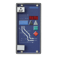
Figure 3.11: Front panel MRI1-SR
SELECT/RESET
ENTER
TRIP
t
I
MRI1-IRER
L1 L2 L3 E
RS
Q
I
P
I
PHASE
EARTH
I >
E
I >>
E
t
I >>
E
t
I>>
I>>
I>
t
CHAR I>
I>
t
I >
E
U >
E
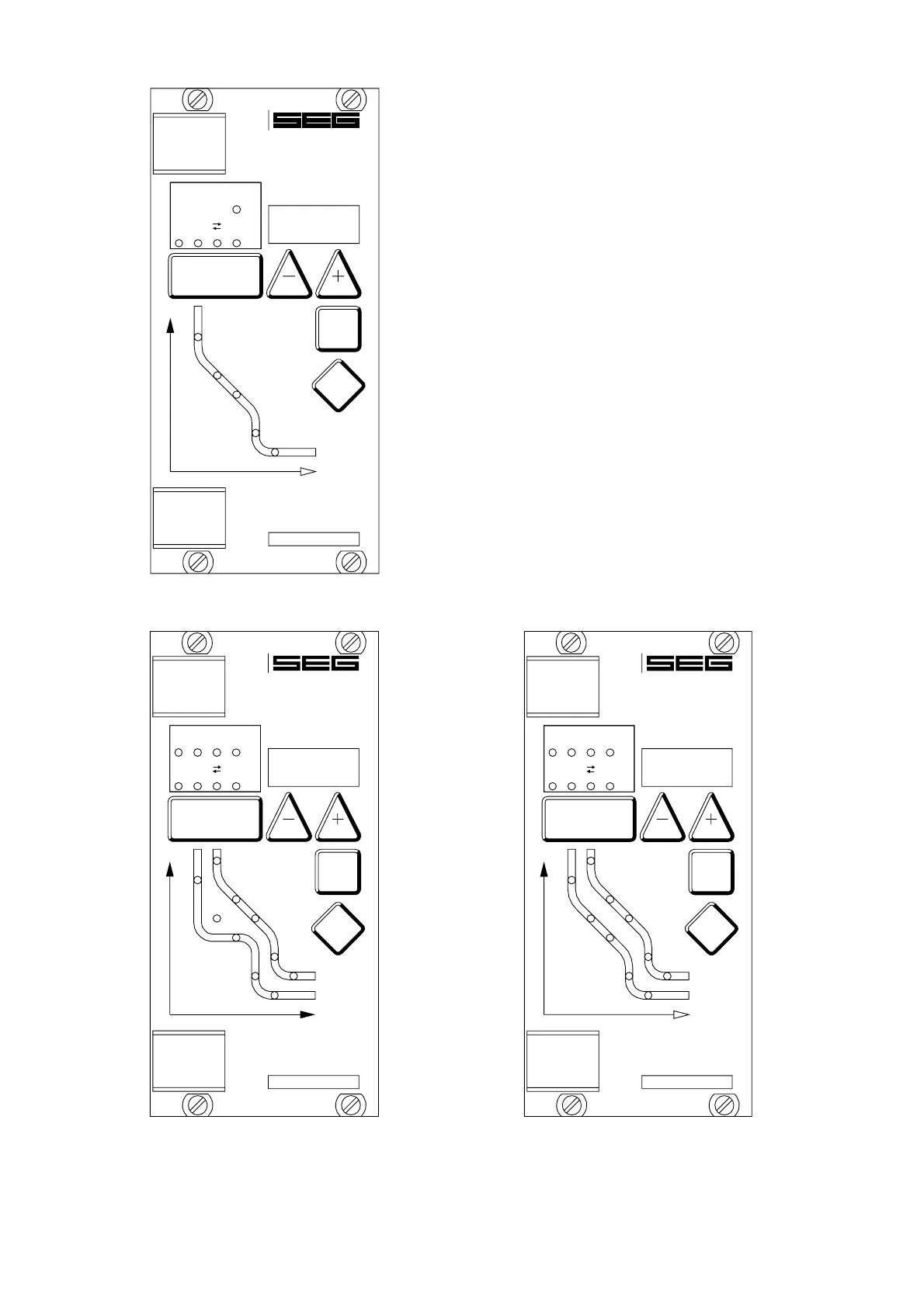
Figure 3.12: Front panel MRI1-IRER/IRXR
and MRI1-IER/IXR
3.3 LEDs
The LEDs left from the display are partially bi-colored,
the green indicating measuring, and the red fault indi-
cation.
MRI1 with directional addition have a LED (green- and
red arrow) for the directional display. At pickup/trip
and parameter setting the green LED lights up to indi-
cate the forward direction, the red LED indicates the
reverse direction.
The LED marked with letters RS lights up during setting
of the slave address of the device for serial data com-
munication.
The LEDs arranged at the characteristic points on the
setting curves support the comfortable setting menu se-
lection. In accordance with the display 5 LEDs for
phase fault overcurrent relay and 5 LEDs for earth-fault
relay indicate the corresponding menu point selected.
SELECT/RESET
ENTER
TRIP
t
I
MRI1-IRSR
L1 L2 L3 E
RS
Q
I
P
I
PHASE
EARTH
I >>
E
I>>
I>
I >
E
CHAR I
t
I >
E
I >>
E
t
t
I>>
I>
t
CHAR I>
E
Figure 3.13: Front panel MRI1-IRSR; MRI1-IRE/IRX
and MRI1-ISR
 Loading...