26 TD_MRI1_06.05_GB
6.4.2 Example of test circuit for MRI1
relays without directional feature
For testing MRI1 relays without directional feature,
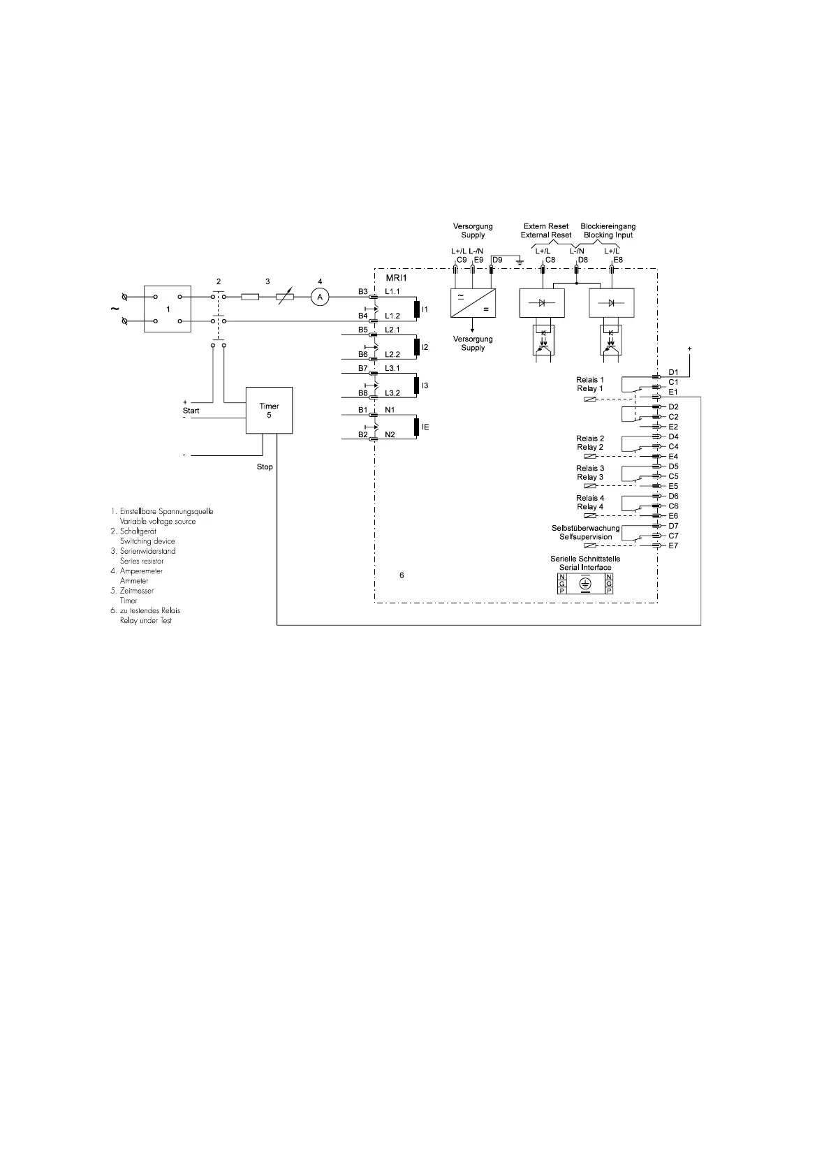
only current input signals are required. Figure 6.1
shows a simple example of a single phase test circuit
with adjustable current energizing the MRI1 relay un-
der test.
Figure 6.1: Test curcuit
6.4.3 Checking the input circuits and
measured values
Inject a current, which is less than the relay pickupcur-
rent set values, in phase 1 (terminals B3-B4), and
check the measured current on the display by pressing
the push button <SELECT>. For a relay with rated cur-
rent In = 5A, for example, a secondary current injec-
tion of 1A should be indicated on the display with
about 0.2 (0.2 x In). The current can be also injected
into the other current input circuits (Phase 2: terminals
B5-B6, Phase 3: terminals B7-B8. Compare the dis-
played current value with the reading of the ammeter.
The deviation must not exceed 3% or 1 % In. By using
an RMS-metering instrument, a greater deviation may
be observed if the test current contains harmonics. Be-
cause the MRI1 relay measures only the fundamental
component of the input signals, the harmonics will be
rejected by the internal DFFT-digital filter. Whereas the
RMS-metering instrument measures the RMS-value of
the input signals.
6.4.4 Checking the operating and
resetting values of the relay
Inject a current which is less than the relay set values in
phase 1 of the relay and gradually increase the cur-
rent until the relay starts, i.e. at the moment when the
LED I> and L1 light up or the alarm output relay I> is
activated. Read the operating current indicated by the
ammeter. The deviation must not exceed 3 % of the set
operating value or 1 % In.
Furthermore, gradually decrease the current until the re-
lay resets, i.e. the alarm output relay I> is disengaged.
Check that the resetting current is smaller than 0.97
times the operating current.
Repeat the test on phase 2, phase 3 and earth current
input circuits in the same manner.(Accuracy of earth
current measuring ±3% of measuring value or
0.1% of In for E-type; 0.01% of In for X-type).


 To Next Page
 Loading...