EasyManua.ls Logo

SEGA ENTERPRISES AFTER BURNER User Manual

Default Icon
34 pages
To Next Page IconTo Next Page
Page #1 background imageLoading...
Page #1 background image
1st PRINTING- JS
UPRIGHT
TYPE
OWNER’S
MANUAL
SEGA
ENTERPRISES/LTD
MANUAL
No.
420
-
5798
-
01 AT
Question and Answer IconNeed help?

Do you have a question about the SEGA ENTERPRISES AFTER BURNER and is the answer not in the manual?

SEGA ENTERPRISES AFTER BURNER Specifications

General IconGeneral
Release Year1987
GenreCombat Flight Simulator
OrientationHorizontal
ControlsThrottle
CPUMotorola 68000
Sound ChipYM2151
Resolution320 x 224

Summary

Introduction to the Owner's Manual

Prevention of Counterfeiting and Conversion

Installation Place Precautions

Arcade Machine Part Identification

Control Unit Access Procedure

Handle Unit Calibration Guide

Motor Brush Replacement Guide

Throttle Unit Adjustment Procedure

IC Board Removal Instructions

Service Switch Functionality

DIP Switch Configuration Options

EPROM and Mask ROM Locations

After Burner Parts Breakdown

Final Assembly Diagram (Part 1)

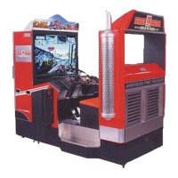
Diagram illustrating the first half of the main assembly parts for the After Burner U/R.

Handle Grip Assembly (TX-1335) Details

Detailed breakdown and part numbers for the After Burner handle grip assembly (TX-1335).

Control Unit Assembly (TX-1350) Diagram (Part 1)

Diagram of the first half of the control unit assembly (TX-1350), showing part placements.

Sub-Controller Assembly (TX-1351) Diagram (Part 1)

Diagram for the first half of the sub-controller assembly (TX-1351), illustrating component locations.

Shock Mechanism Assembly (TX-1352) Diagram (Part 1)

Diagram for the first half of the shock mechanism assembly (TX-1352), detailing its parts.

Control Unit Assembly (TX-13001) Diagram (Part 1)

Diagram of the first half of the control unit assembly (TX-13001), showing internal components.

Throttle Unit Assembly (TX-14001) Diagram (Part 1)

Diagram of the first half of the throttle unit assembly (TX-14001), illustrating its parts.

Power Supply Assembly (TX-40001 AT) Diagram (Part 1)

Diagram of the first half of the power supply unit assembly (TX-40001 AT), showing component placement.

After Burner Wiring Diagram

Related product manuals