9
MxI
c
D
a
b
A EA III - IV 106 152 10 160 M12 x 65
B FA III 106 152 10 160 M12 x 65
IV 104 194 10 180 M12 x 65
C III 106 152 10 160 M12 x 65
IV 104 194 10 180 M12 x 65
D GA I 98 140 10 150 M8 x 55
II 106 152 10 160 M12 x 65
III - IV 104 194 10 180 M12 x 65
E HA I 98 140 10 150 M8 x 65
II 106 152 10 160 M12 x 65
III - IV 104 194 10 180 M12 x 65
F I 126 180 12 190 M12 x 65
I - IV 138 196 15 200 M16 x 80
G JA I - II 138 196 15 210 M16 x 80
III - IV 138 196 15 210 M16 x 80
H KA I - II 160 230 15 250 M16 x 80
III - IV 160 230 15 250 M16 x 80
J I - III 184 262 15 290 M16 x 80
IV 184 262 15 290 M16 x 80
K LA I - IV 192 274 15 300 M16 x 80
L MA, NA I - IV 200 286 15 310 M16 x 80
M I - IV 230 328 15 370 M16 x 80
N PA I -III 242 344 20 380 M20 x 100
P I -III 288 410 20 460 M20 x 100
Q QA I -III 288 410 20 460 M20 x 100
R RA I -III 288 426 20 480 M20 x 100
S TA I 350 350 25 430 M20 x 135
T I 400 400 30 480 M20 x 135
U I 450 450 30 530 M20 x 140
V I 550 550 30 680 M20 x 140
W I 640 640 30 780 M20 x 140
X I 720 720 60 900 M24 x 180
Y I 860 860 60 1050 M24 x 180
Z I 950 950 60 1140 M24 x 180
SEMPELL SERIES VSE/VSR FULL LIFT AND NORMAL SAFETY RELIEF VALVE
OPERATING INSTRUCTIONS
5.5 Dismantling the safety valve
To remove or disassemble a possibly mounted
pneumatic actuator A160 see operating
instruction MA.270.07.xxxx E.
Remove lead seal. Dismount cap (13). Remove
split pin (29) and lifting nuts (12) or loosen and
remove checked lifting nuts (12). Measure and
record distance between upper edge of spindle
(7) and tightening screw (11). Loosen lock
nut (28) and release spring (10) by means of
tightening screw (11).
Loosen nuts (9.1) and lift off bonnet (8). Remove
spring (10), cooling spacer (15) (if installed),
gasket (26), spindle (7) and guide bush (6). In
case of VSR 1 and VSR 2 do not change position
of the adjusting ring (14); mark, if necessary.
Remove disc (4) and ball (18); at orifice letter
SKB: D - W drive out dowel pin (19). The guide
piston (5) will not be disassembled. Dismount
cap (13) with lever (36) only if necessary.
6 ASSEMBLY
For SKB D - W: fasten disc (4) and ball (18) by
means of dowel pin (19) to the spindle (7).
Insert guide bush (6); for VSR 1 and VSR 2
observe marked position of the adjusting ring
(14). Insert disc (4), ball (18) and spindle (7).
Put over cover (16) possibly with slide ring (43).
According to design put on cooling spacer (15),
split ring (20), stop bush (21), distance bush
(22), pressure bush (23), spring stop (24), spring
(10), spring plate (25) and roller bearing (48).
Put on bonnet (8) and screw tight with
hexagonal nuts (9.1). Prestress spring (10) by
means of tightening screw (11) onto the same
dimension as measured before disassembling;
thus the same set pressure as before. Secure
tightening screw (11) with lock nut (28). Screw
on two lifting nuts (12) at the upper end of the
spindle (7) and secure them or screw on lifting
nuts (12) and tighten with split pin (29).
Mount cap (13) and lead seal. Check easy
motion and function of the lever (36) with fork
(31). If available, mount supplementary loading.
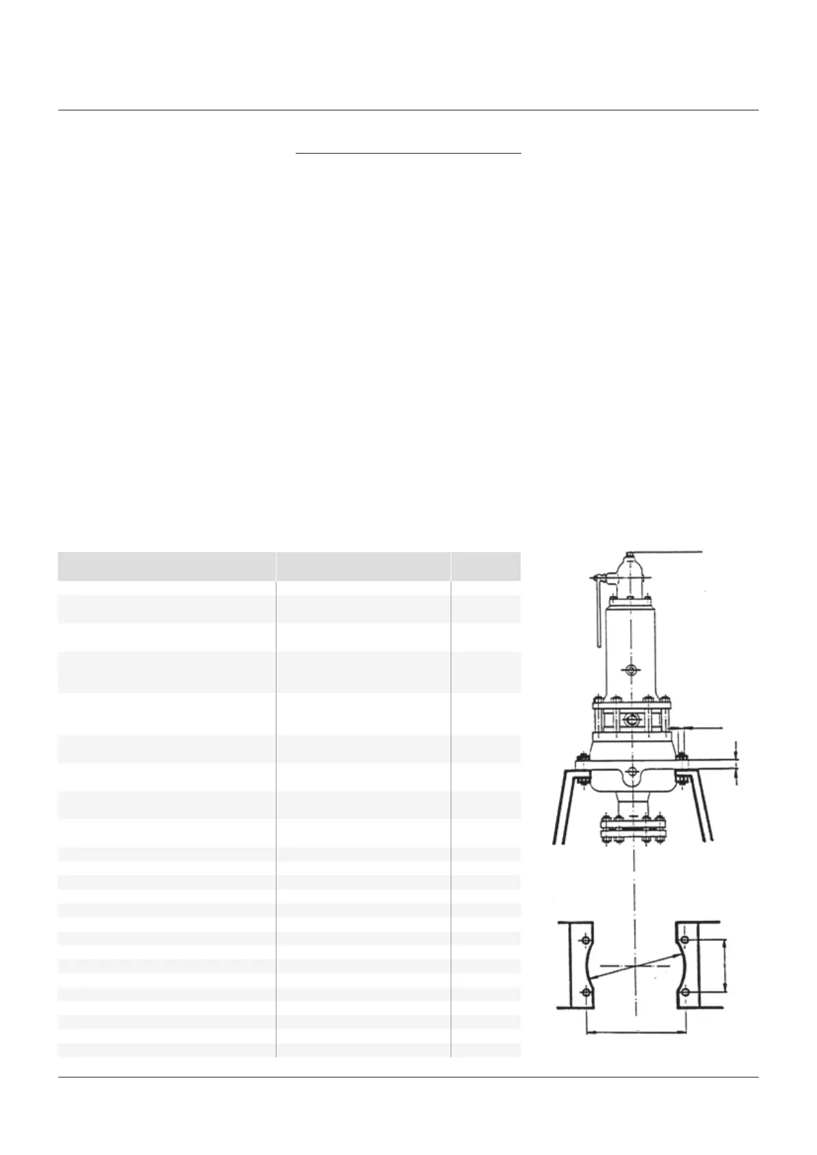
7 DIMENSIONS FOR MOUNTING BRACKET
Orifice letter SKB Dimensions in mm
Sempell API Group a b c D Thread
 Loading...