9
WWW.SENIXTOOLS.COM
ASSEMBLY
ASSEMBLY
WARNING!
CAUTION!
Remove the battery before inspecting,
adjusting, performing maintenance, or
cleaning the unit.
ASSEMBLY OF GUIDE BAR AND
SAW CHAIN
1. Loosen the cover release knob to release
the chain sprocket cover (Figure 1).
Remove the chain sprocket cover.
1. Release knob
2. Wearing protective gloves, wrap the saw
chain around the guide bar, making sure
that the teeth are aimed in the direction of
rotation (Figure 2). The chain should be
properly set in the slot running along the
entire outside edge of the guide bar.
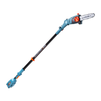
3. Insert the guide bar and chain into the
mount on the pole saw (Figure 3). In
the process, guide the chain around the
pinion and hang the guide bar in the chain
tensioning bolts.
4. Adjust the chain tension. Mount and hand-
tighten the chain sprocket cover with the
retaining nut.
Always wear protective gloves when
handling saw chains.
Figure 1 - Release knob
Figure 2 - Correct teeth direction
Figure 3 - Guide bar and chain installation
1
TENSIONING THE CHAIN
WARNING!
CAUTION!
Remove the battery before inspecting,
adjusting, performing maintenance, or
cleaning the unit.
Always wear protective gloves when
handling saw chains.
1.Loosen the retaining nut of the chain
sprocket cover by a few rotations.-
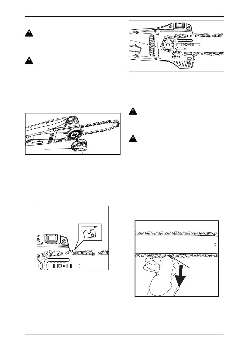
2.Adjust the chain tension by rotating the
Tension Adjustment Knob (the outermost
knob on the cover release knob). Clockwise
rotation increases the chain tension;
counter-clockwise rotation reduces the
chain tension. The saw chain is correctly
tensioned if it can be raised approximately
2 mm from the center of the guide bar
(Figure 4).
Figure 4 - Correct chain tension
2 mm
 Loading...