Do you have a question about the Sensit GOLD G2 and is the answer not in the manual?
Safety notices, including warnings about hazardous situations and sensor care.
Guidelines for battery replacement and instrument servicing in safe areas.
List of standard accessories that come with the instrument.
Details on optional accessories and parts for replacement.
Information on selecting the correct calibration kit.
Overview of the SENSIT® GOLD G2's detection capabilities and sensor types.
Details on display, LEDs, sampling, and audible/visual alarms.
Factory preset alarm points for various gases and instrument certifications.
Technical details on sensor types, resolution, range, and accuracy.
Physical dimensions, weight, operational and storage temperatures, and battery life.
Details on ATEX, UL, and other safety certifications for the instrument.
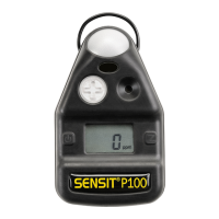
Identification of key external components like probe connector, sensor cap, display, and buttons.
Description of the graphic display and alarm LEDs on the instrument.
Details on instrument construction, battery type, and battery life.
Information on infrared communication and the flexible gooseneck for sampling.
Explanation of the graphic display functionality and the three operational buttons.
Description of the semiconductor sensor for combustible gases and its measurement capabilities.
Details on optional sensors for oxygen, CO, H2S, and HCN.
Information on the internal pump, its protection filters, and indicators.
How to interpret the battery strength icon and low power warnings.
Step-by-step guide for safely replacing the instrument's batteries.
Steps for powering on the instrument and the system checks performed.
Details on the information displayed during the instrument's startup sequence.
Handling display errors, CAL DUE messages, and inoperable sensors.
Explanation of gas units (LEL, PPM, % VOL) and auto-ranging features.
Procedure for testing sensor cap and tubing integrity for proper flow.
Instructions for manual zeroing and safe use of the hot air probe.
Using the extension adapter for high area sampling.
How the instrument indicates gas presence and alarm conditions via LEDs and sound.
Details on standard LED indicators and alarm thresholds for different gases.
Information on gas sensor sensitivity and potential cross-sensitivity issues.
How to mute and control alarms, and indications of unsafe conditions.
Using the tick rate and bar graph for locating small leaks.
How to save readings and the instrument's memory capacity.
Guidelines for sampling, understanding NSR/NSC readings, and dark area usage.
Procedure for turning off the instrument after use.
Using the Bar Hole Test feature to pinpoint underground leaks.
Step-by-step instructions for performing a Bar Hole Test.
How to restart a test or cancel and return to the working display.
Understanding NSR/NSC readings and using hydrocarbon filters.
Procedure for entering the Leak Search mode and initial setup.
How to zero the instrument and mute alarms during Leak Search.
Steps to exit the Leak Search mode and return to the work display.
Using the Purge Mode for purging lines in and out of service.
Procedure for entering and conducting a Purge Test.
Steps to exit the Purge mode and return to the work display.
Procedure to enter the Work Display Peak Readings mode.
How to reset peak readings and exit the WDPK mode.
Procedure to enter and start the Carbon Monoxide (CO) test.
Details on the timed test, detected CO levels, and data storage.
Verifying instrument accuracy by exposing it to test gas.
Understanding CAL DUE messages and when to check calibration.
Introduction to the User Menu categories and standard fields.
Descriptions of Show Time, Set Clock, Print, Bump Test, Cal, O2 Test, Gas Type.
Details on Cal Log, Ses Log, BH Log, Smart-Cal, Cal Due, Auto Log, CF Log.
How to view the current date and time on the instrument.
Procedure for setting the instrument's date and time.
Instructions for printing logs and test results using an IR printer.
Procedure for performing an automatic sensor bump test.
Instructions for calibration and performing an oxygen sensor test.
How to change the primary gas type (Natural/Propane) for readings.
Viewing and printing the instrument's calibration history.
Viewing and printing saved gas readings and session data.
Viewing bar hole test logs, including record number, date, and concentrations.
Procedure for communicating with the Smart-Cal calibration station.
Displaying calibration due dates and next calibration reminders.
Automatic saving of peak readings and retrieving autolog events.
Instructions for conducting the CF Test with a hot air flue probe.
Understanding CF test results, including N/A readings and proper conditions.
Viewing and printing the most recent CF test data.
General steps for calibrating the instrument with certified gases.
Definitions of terms like AUTO CAL, V/V, LEL, PPM, and SMART-CAL.
Accessing and starting the AUTO CAL mode for instrument calibration.
Steps for the auto calibration test, including gas connection and pass/fail indication.
Calibrating individual sensors and updating calibration due dates.
Handling calibration failures and accessing the SMART-CAL system.
Procedure for manually calibrating the CO sensor with 100ppm CO/Air.
Procedure for manually calibrating the H2S sensor with 25ppm H2S/Air.
Procedure for manually calibrating the HCN sensor with 10ppm HCN/N2.
Procedure for calibrating the combustible gas sensor to 50% LEL Methane.
Procedure for calibrating the combustible gas sensor to 100% Methane.
Procedure for calibrating the combustible gas sensor to 1.1% Propane (50% LEL).
Testing the oxygen sensor's reaction to a gas void of oxygen.
Definitions for Contrast, LEL Mode, LEL resolution, and sensor compensation.
Definitions for calibration reminders, logs, and alarm settings.
Definitions for power off, purge time, bump test, and log erasing.
Chart detailing expert settings for contrast, LEL mode, and alarm limits.
Chart detailing expert settings for power off, purge time, and language.
Details on the warranty period for materials, workmanship, and specific sensors.
Exclusions from warranty, proof of purchase, and service procedures.
SENSIT Technologies contact details for service and support.
| Display | LCD |
|---|---|
| Power Source | Rechargeable battery |
| Operating Temperature | -20°C to 50°C |
| Alarm | Audible and visual |
| Detection Range | 0-100% LEL |
| Battery Life | Up to 12 hours |
| Measurement Range | 0-100% LEL |
| Response Time | <15 seconds |
| Sensor Type | Catalytic Bead (LEL) |