FT 20 RL
Laserowy czujnik kontrastu /
laser contrast switch
- Precyzyjne wykrywanie ma³ych markerów /
accurate detection of small printing marks
- Laser 650 nm / laser red light 650 nm
- Strefa dzia³ania 150 mm / scanning distance 150 mm
- Zdalne sterowanie / external teach for setting and to
disable the teach button
- Laser klasy 2 / laser protection class 2
- Ma³a obudowa / compact housing
- Przycisk ucz¹cy / Teach In
- Wybór funkcji wyjcia NO/NC / N.O. - N.C. selectable
Ustawianie czu³oci
1.) Przysuñ obiekt do czujnika. ¯ó³ta i zielona dioda wiec¹ siê.
2.) Nacinij przycisk przez 3s a¿ obie diody zaczn¹ migaæ
jednoczenie. (Pierwszy krok uczenia zakoñczony). 3.)
3.) Odsuñ obiekt od strefy dzia³ania.
4.) Nacinij przycisk przez 1s (Czujnik uczy siê t³a).
Zielona LED miga i zostaje w³¹czona, (drugi krok uczenia
zakoñczony). Czujnik jest gotowy do pracy.
Ustawianie czu³oci z obiektem
1.) Przysuñ obiekt do czujnika. ¯ó³ta i zielona dioda wiec¹ siê.
2.) Nacinij przycisk przez 3s a¿ obie diody zaczn¹ migaæ
jednoczenie. (Pierwszy krok uczenia zakoñczony).
3.) Pozostaw obiekt w strefie dzia³ania. Nacinij przycisk przez 1s
(Czujnik uczy siê t³a). Zielona LED miga i zostaje w³¹czona, (drugi krok
uczenia zakoñczony). Czujnik jest gotowy do pracy.
Dynamiczne ustawianie czu³oci w czasie trwania procesu detekcji
1.) Przysuñ obiekt do czujnika. ¯ó³ta dioda i zielona dioda wiec¹ siê.
2.) Czujnik musi widzieæ jedynie badany proces! Nacinij przycisk przez
3s a¿ obie diody zaczna migaæ jednoczenie. 3 s
3.) Nacinij przycisk przez czas co najmniej jednego cyklu badanego
procesu. 1 cykl
a:) Zielona dioda miga i zostaje w³¹czona, oba kroki uczenia
s¹ zakoñczone. Czujnik jest gotowy do pracy.
b:) Obie diody migaj¹ jednoczenie: Czu³oæ czujnika nie zosta³a
prawid³owo wyregulowana. Powtórz czynnoci regulacji.
Zmiana funkcji wyjcia NO/NC
1.) Nacinij przycisk przez czas co najmniej 13 s. 13 s
a¿ obie diody zaczn¹ migaæ naprzemiennie.
2.) Zwolnij przycisk: Zielona dioda wieci siê.
3.) Podczas gdy dioda siê wieci wybraæ funkcjê wyjcia przez
przyciskanie przycisku.
Je¿eli przycisk jest nie naciskany przez 10s aktualna funkcja wyjcia
jest zapamiêtana. Czujnik jest gotowy do pracy.
Powrót do ustawieñ fabrycznych (domylnych)
1.) Brak obiektu w strefie dzia³ania czujnika.
Nacinij przycisk przez 3s a¿ obie diody zaczna migaæ jednoczenie.
3 s
2.) Brak obiektu w strefie dzia³ania czujnika. Nacinij przycisk przez
1s.
1 s. Czu³oæ czujnika jest maksymalna (ustawienie fabryczne).
Zdalne sterownie czujnikiem przewodem wyprowadzenie ET (pin 2)
10 ... 30 VDC - funkcja przycisku w³¹czona ( do³¹czenie ET do pin1 )
0 ... 2,5 VDC - blokada przycisku ( do³¹czenie ET do pin 3 )
brak po³¹czenia ET - tryb pracy bez aktywacji zdalnego sterowania
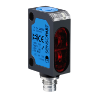
nadajnik i
odbiornik /
light emitter and
receiver
Sensitivity setup
1.) Line up sensor to the object. Yellow LED and green LED are on.
2.) Press the button 3 s until both LED´s are flashing synchronously.
(The first threshold is teached).
3.) Put the object out of the scanning area.
4.) Press the button 1 s (learning of backround).
The green LED flashes and stays on: the second threshold is
teached, the sensor is ready to operate.
Sensitivity setup only with object
1.) Line up sensor to the object. Yellow LED and green LED are on.
2.) Press the button 3 s until both LED´s are flashing synchronously.
(The first threshold is teached).
3.) Leave the object in the scanning area, press the button for 1 s. The
green LED flashes and stays on, the second treshold is teached, the
sensor is ready to operate.
Dynamic sensitivity setup at a running process
1.) Line up sensor to the object. Green LED on, yellow LED is
undefined.
2.) The chosen running process must be the only thing in the scanning
area! Press the button 3 s until both LED´s are flashing synchronously.
3 s
3.) Press the button for a minimum of one process cycle is completed.
1 cycle
a:) The green LED flashes and stays on: both thresholds have been
teached, the sensor is ready to operate.
b:) Both LED´s are flashing synchronously: the sensor can not detect
the object, no thresholds are teached
N.O./N.C. setup
1.) Press the button for 13 s.
13 s: Both LED´s are flashing
alternately.
2.) Release the button: the green LED is on.
3.) During the green LED is on, the output is inverted by pressing the
button.
If the button is not pressed during 10 s the present output function is
saved, the sensor is ready to operate.
To return to factory setting (default)
1.) No object in sensing area.
Press the button 3 s until both LED´s are flashing synchronously.
3 s
2.) No object in sensing area. Press the button 1 s.
1 s. The sensor is set to maximum sensitivity.
External Teach (ET)
10 ... 30 VDC - same function as button
0 ... 2,5 VDC - locked (disable teach button)
not connected - operating mode
Strefa dzia³ania (mm) 200 200 200 200
max. distance (mm)
Schemat po³¹czeñ (strona nastêpna) 1212
wiring diagram (see reverse)
Typ / Sposób zamawiania FT 20 RL- FT 20 RL- FT 20 RL- FT 20 RL-
type / order ref.
PSM4 NSM4 PSK4 NSK4
Wyprowadzenie Konektor Konektor Kabel Kabel
connection con. con. cable cable
Funkcja wyjcia (ustawiana) P N P N P N P N P N P N
output (preset)
N.O. N.O. N.O. N.O.
¿ó³ta LED /
yellow
LED
zielona LED /
green
LED
Przycisk /
button