© Sensortech Systems, Inc. 2016 Page 8 of 16 Rev.7-2016
Leveling the Rollers:
Lay a level or straight edge across the six rollers near their ends.
Shim the two outer rollers’ bearing assemblies so that they are level.
Shim the remaining four rollers’ bearing assemblies so that each roller is within 0.01 inches
(.25mm) of level.
Lay the level along the first roller. Shim its bearing assembly on the other side so that it is level
lengthwise.
Lay a level across the six rollers near their ends.
Shim the last roller’s bearing assembly so that it is level with the first roller.
Shim the remaining four rollers’ bearing assemblies so that each roller is within 0.01 inches
(.25mm) of level.
Use a feeler gauge to measure the space from the top of Sensor to bottom of a board or use the
ST-2200 Standardization Plate for board alignment. To make a feeler gauge for air gap
alignment, cut two 12 in. (30 cm) lengths of 0.25 in. (6.35 mm) square or round rod and place on
Sensor below the Standardization Plate and adjust the beam until the rods just touch the bottom
of the Standardization Plate. Ensure both ends of the Standardization Plate are coplanar to the
tops of the Sensor. Adjust the Sensor mounting Beam and adjacent 4-6 rollers until the Sensor is
coplanar to the rollers and the rollers are level to each other.
The top surface of the IMPS Sensors should be 0.25 +/- 0.02 inches (6 +/- 0.5mm) from the bottom of the board.
Mount the sensor 0.125 inches (3mm) down from the surface of the bracket. This protects the sensor from the
leading board edge.
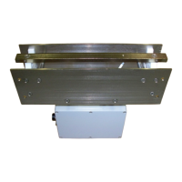
IMPS Sensors
The maximum runout for each of the three rollers preceding
and following the sensors is 0.02 inches (0.5 mm).
Sensor
 Loading...