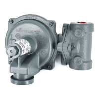
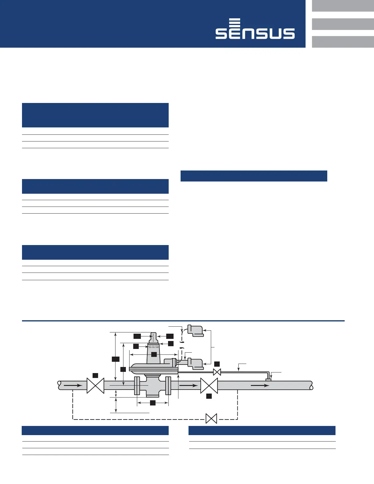
3a 1a
3
D1
C
Inlet
Minimum
Service Space
D
4"
8"
F
Bypass (if required)
Remote Vent (if required)
1" NPT
B
A
Control Line
Connection
Control Line
1/4" NPT
Outlet
Vent Cap
3
E
Model D D1 E
461-12S 13-1/4" – 14"
461-8S – 18-3/8" 10-3/16"
461-S (12") – 19-1/2" 14-1/4"
461-S (8-1/2") – 19-1/2" 11"
Regulator Body Type F (Face to Face)
Screwed 6-1/2"
Flanged ANSI 125 FF 10"
Flanged ANSI 250 FF 10-1/2"
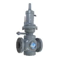
2
Maximum
Working
Regulator Body Pressure
Body Type Materials of Body
2" Screwed only Cast Iron 250 psi
Flanged ANSI 125 Cast Iron 175 psi*
Flanged ANSI 250 Ductile Iron 575 psi*
Flanged ANSI 300 Cast Steel 720 psi*
Maximum Inlet Pressures
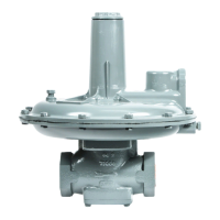
Regulator Models 461-S, 461-8S, and 461-12S are excellent
general purpose gas pressure regulators for intermediate and
larger loads. Use them for natural gas, air, dry CO
2
, propane,
butane and other gases.
*Carefully note the following exceptions to the above,
based on diaphragm size:
Diaphragm Diaphragm Maximum Inlet
Size ID Case Material Pressure
12” Cast Iron 100 psi
8-1/2” Cast Iron 175 psi
12” Aluminum 100 psi
8” Aluminum 175 psi
Valve material selection is limited by inlet pressure and
differential:
Valve Maximum Inlet Maximum Pressure
Material Pressure Rating Differential Rating
Buna-N 575 psi 250 psi
Poly-U Red 720 psi 400 psi
Poly-U Tan 1200 psi 600 psi
Typical Arrangement
and Dimensions
(Indoor or Outdoor Installation)
Installation and Start-Up
1 Thoroughly purge inlet piping to remove dirt and debris that could
damage the regulator or impair its operation. If this cannot be
done, a filter or strainer should be installed ahead of the regulator.
(see bulletin RDS-1498, Regulator Pressure Ratings).
Make certain that inside of the regulator and piping are free
of dirt, foreign matter, and other debris.
2 Install the regulator. Make certain flow through the regulator is
in the correct direction. High pressure connects to the inlet
side. Be sure that shipping screens or covers, if used, are
removed.
On flanges, tighten bolts evenly. On screwed connections,
apply pipe dope to male threads only. Where required,
the regulator may be inverted.
CAUTION
It is the user's responsibility to assure that all regulator vents
and/or vent lines exhaust to a non-hazardous location away from
any potential sources of ignition. Where vent lines are used,
it is the user's responsibility to assure that each regulator is
individually vented and that common vent lines are not used.
3 The vent connection is an escape path for flammable gas and
it must be located and/or piped so that potential discharge
occurs in a safe area away from buildings, open flames,
collection areas, arcing devices, etc.
Regulators that are installed indoors, or in a non-vented area
must be vented to the outside. Simply run vent piping from
the regulator vent connection to a non-hazardous location
on the outside away from any potential sources of ignition.
The vent piping must be connection size or larger and piped
to a safe area.
The outlet of the vent piping must allow for the free and
unobstructed passage of air and gas, and must be protected
against the potentials listed in instructions.
Installation and Maintenance Instructions
Model 461-S, 461-8S, and 461-12S Regulator
 Loading...