To Service Single Seat Balanced
Valve Assembly
1 Remove seal cap 1, 1a or 1b. Mark or measure position
of adjustment 3 or 3a. Use this to return adjustment to this
setting during reassembly.
On 461-12S remove adjustment 3 and spring 9.
On 461-8S release adjustment 3a and remove cover 5,
button 7a, and spring 9.
On 461-S release adjustment 3a and remove cover 8,
button 7b, and spring 9.
2 Remove bottom inspection plate 14.
3 Remove locknut 12e, then slip off valve 12d and retainer 12c.
Orifice 18 can be removed with socket wrench (1-1/2" hex
deep socket.) Reassemble in reverse order.
4 If it should be necessary to remove stem 12b or valve guide
30, do so by first removing lower diaphragm case 24
(steps 2 through 7 under “To Service Diaphragm” below).
Use socket wrench for 30 (1-1/2” hex deep socket).
5 Note – single seat balanced valve does not require
any lock-up adjustment.
6 Note : orifice 18 must be same size as stem guide 30
(1” 18 with 1” 30 and 11/16” 18 with 11/16” 30).
Do not use 11/16” size of one with 1” size of the other.
7 Replace bottom inspection plate 14.
8 Replace parts removed under Step 1 above and return
adjustment to original setting.
To Change Spring
1 Remove seal cap 1, 1a or 1b.
On 461-12S remove adjustment 3 and spring 9.
On 461-8S release adjustment 3a and remove cover 5,
button 7a, and spring 9.
On 461-S release adjustment 3a and remove cover 8
button 7b, and spring 9.
2 Insert the new spring. Be sure it nests correctly onto part 11b.
3 Replace remaining parts removed under Step 1.
To Service Diaphragm
1 Remove seal cap 1, 1a or 1b. Mark or measure position
of adjustment 3 or 3a. Use this to return adjustment to this
setting during assembly.
On 461-12S remove adjustment 3 and spring 9.
On 461-8S release adjustment 3a and remove cover 5,
button 7a, and spring 9.
On 461-S release adjustment 3a and remove cover 8,
button 7b, and spring 9.
2 Remove bolts 22 and then carefully remove upper
diaphragm case 21.
3 Turn diaphragm assembly counterclockwise
(this unscrews 11h from 12b) and remove.
4
To Service Double Seat Balanced
Valve Assembly
1 Remove seal cap 1, 1a, or 1b. Mark or measure position of
adjustment 3 or 3a. Use this to return adjustment to setting
during reassembly.
On 461-12S remove adjustment 3 and spring 9.
On 461-8S release adjustment 3a and remove cover 5,
button 7a, and spring 9.
On 461-S release adjustment 3a and remove cover 8,
button 7b, and spring 9.
2 Remove bottom inspection plate 14, and unscrew valve
assembly intact from diaphragm assembly
(12b unscrews from 11h).
3 Unscrew orifice 18 with socket wrench (1-1/2" hex deep
socket). Remove orifice 18 and valve assembly intact through
bottom opening.
4 If valve assembly does not require changes, replace without
disturbing set screw 12g (top end of 12b screws onto 11h)
until it bottoms and should then be backed off 1/2 turn to 1
full turn).
5 If new parts are needed, disassemble valve assembly by
loosening set screw 12g and unscrewing 12h from 12b,
and then unscrewing nut 12e and part 12j.
6 Replace parts as required, then reassemble upper half valve
assembly (parts 12a, 12b, 12c, 12d, 12e) and lower half
(parts 12f, 12g,
12h, 12c, 12d, 12j).
7 Insert through bottom opening:
a. upper half valve assembly – screw 12b onto 11h until it
bottoms, then back off 1/2 to 1 full turn.
b. orifice 18 – screw firmly into place.
c. lower half valve assembly – screw onto upper half by
3 or 4 turns (12h screws onto 12b).
8 Make the valve lock-up adjustment. Seat the upper valve
against orifice 19 while screwing up the lower half valve
assembly (12h screws onto 12b) until the lower valve is
seated against 18. Then, firmly tighten set screw 12g.
To seat the upper valve against orifice 19 either reach it
through the body side opening or remove diaphragm
assembly and pull top end of stem 12b upwards.
Tighten 12g with screwdriver or Allen wrench through body
side opening. If necessary, turn the entire valve assembly
(carefully – do not disturb adjustment) to face 12g toward side
opening. 12g must tighten against flat area at top of 12h to
correctly lock the adjustment.
9 Screw entire valve assembly up (top of 12b screws onto lower
end of 11h) until it bottoms.
Then back off 1/2 to 1 full turn – this is important.
10 Replace bottom inspection plate 14. Engage pin in 13
with slot in lower end of 12j, then rotate 14 until holes line up
and install cap screws 16.
11 Replace parts removed under Step 1 above and return
adjustment to original setting.
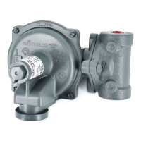
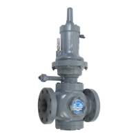
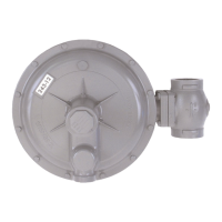
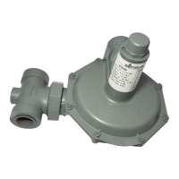
Installation and Maintenance Instructions
Model 461-S, 461-8S, and 461-12S Regulator
 Loading...