Do you have a question about the SEW-Eurodrive DOP11C-51 and is the answer not in the manual?
Outlines user responsibilities for safety compliance and qualified personnel.
Defines the product's intended use and prohibited applications.
States the product must not perform safety functions without higher-level systems.
Instructions for electrical installation, safety measures, and grounding.
Details the connection ports on the underside of DOP11C-51, -71, -101.
Provides essential guidelines for installing the basic unit, including cable management.
Details requirements for EMC-compliant installation, including cable shielding.
Information specific to UL-labeled panels regarding suitability and expansion units.
General guidance on how to mount the operator panel, depending on the design.
Step-by-step instructions for mounting specific operator panel models.
Step-by-step instructions for mounting specific operator panel models.
Step-by-step instructions for mounting specific operator panel models.
Safety precautions and information for connecting the operator panel.
Details the installation diagram and cable connection order for the operator panel.
Details the connection of the operator panel to an engineering PC via Ethernet.
Provides instructions and safety notices for connecting the voltage supply.
Explains how to start the operator panel and access the service menu.
Details the procedure to open the service menu after a project has been uploaded.
Provides pin assignment details for serial connections (COM1, COM2, COM3, COM4).
Details the pin assignments for the serial communication interfaces.
| Type | DOP11C-51 |
|---|---|
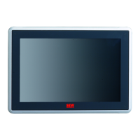
| Category | Control Panel |
| Touchscreen | Yes |
| Protection class | IP65 (front) |
| Operating Voltage | 24 V DC |
| Display | Color TFT |
| Interfaces | USB, Ethernet, RS232, RS485 |
| Operating Temperature | 0°C to 50°C |
| Storage Temperature | -20...+70 °C |
| Weight | 2.5 kg |
| Display diagonal | 10.4 inches |
| Resolution | 640 x 480 pixels (VGA) |