Do you have a question about the SEW-Eurodrive DOP11C and is the answer not in the manual?
Defines the scope and purpose of the operating instructions for the DOP11C panel.
Explains the symbols and structure used for safety notes within the document.
Details the meaning of signal words like DANGER, WARNING, CAUTION, and NOTICE.
Describes the format and purpose of section-related safety notes.
Explains the structure of safety notes embedded directly within instruction steps.
Outlines the conditions for warranty claims, emphasizing adherence to documentation.
States SEW-EURODRIVE's liability limitations regarding non-compliance with documentation.
Lists other relevant SEW-EURODRIVE documentation for comprehensive understanding.
Clarifies that product names mentioned are brands or registered trademarks.
States the copyright and prohibits unauthorized reproduction or distribution.
Provides essential general safety information and precautions for operating the panel.
Defines the qualified personnel required for mechanical and electrical work on the unit.
Specifies the intended industrial and commercial applications for the DOP11C operator panels.
Lists prohibited uses, such as exposure to direct sunlight.
Warns that panels may not execute safety functions without higher-level safety systems.
Discusses bus systems and the risk of unexpected system behavior due to parameter changes.
Specifies required preventive measures like grounding and protection devices like overcurrent protection.
Provides instructions for inspecting shipments for damage and proper storage.
Details essential steps for safe installation, including grounding, cable routing, and handling.
Offers important tips for operating the panel, such as keeping it clean and understanding its readiness.
Covers warranty, cleaning procedures, and the requirement for qualified personnel for repairs.
Addresses local regulations for disassembly and disposal of the operator panel and its components.
Explains how to interpret the unit's type designation and locate its nameplate.
Illustrates the structure of the DOP11C type designation and its components.
Shows an example of the unit's nameplate with key information like type, part number, and serial number.
Lists all items included in the package for the DOP11C operator panel.
Introduces the display and connection overview for specific DOP11C models.
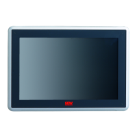
Shows an illustration of the display on the front of the DOP11C-40, -70, and -100 panels.
Illustrates and describes the connections on the bottom and back of the DOP11C-40, -70, and -100 panels.
Introduces the display and connection overview for specific DOP11C models.
Shows an illustration of the display on the front of the DOP11C-120 and -150 panels.
Illustrates and describes the connections on the bottom and back of the DOP11C-120 and -150 panels.
Provides crucial general guidelines for the safe and proper installation of the basic unit.
Details cable routing, cross-sections, shielding, and grounding requirements for installation.
Outlines specific requirements for UL-compliant installation, including warnings and notices.
Specifies the maximum mounting plate thickness and physical space needed for installing the operator panel.
Provides a diagram showing how to connect cables to the operator panel and control cabinet.
Instructs on how to unpack the delivery, check for damage, and handle the protective film.
Details the specific mounting procedures for different DOP11C unit types.
Explains how to correctly connect the panel to the voltage supply, including polarity and grounding.
Covers the preparation steps before connecting the operator panel to other devices.
Outlines necessary precautions and measures before connecting the operator panel.
Details how to connect the panel to frequency inverters via RS485 and to a PC via Ethernet.
Explains the RS-485 connection type, including wiring diagrams and specifications.
Details Ethernet connection, cable specifications, and usage for DOP11C-120/-150.
Highlights critical safety warnings and requirements for a successful startup.
Describes the initial startup procedure, including project upload and accessing the service menu.
Provides a step-by-step guide on how to access and navigate the operator panel's service menu.
Introduces the technical specifications and data tables for the DOP11C series.
Lists the part numbers for each variant of the DOP11C operator panel.
Details the voltage supply requirements, power consumption, and fuses for DOP11C models.
Provides detailed specifications for the display characteristics of each DOP11C model.
Lists dimensions, cutouts, installation depth, protection degrees, and weight for each model.
Specifies operating and storage temperature ranges, and relative humidity limits.
Outlines EMC tests, UL approval, and DNV/NEMA certifications for the operator panels.
Details communication interfaces (serial, Ethernet, USB) and memory specifications.
Provides detailed pin assignments for serial (D-sub), Ethernet (RJ45), and USB connections.
Shows the pinout for the 9-pin D-sub connector for serial communication ports.
Details the pinout for the RJ45 Ethernet connector.
Shows the pinouts for USB-A and USB-B connectors.
Provides information on the RS485/RS422 communication cable, including its diagram and specifications.
Details the cable assembly, pin assignments, and recommended cable type for RS485/RS422.
Introduces dimension drawings for the DOP11C series.
Provides detailed dimension drawings for the DOP11C-40 operator panel.
Provides detailed dimension drawings for the DOP11C-70 operator panel.
Provides detailed dimension drawings for the DOP11C-100 operator panel.
Provides detailed dimension drawings for the DOP11C-120 operator panel.
Provides detailed dimension drawings for the DOP11C-150 operator panel.
Contains the EC Declaration of Conformity for the DOP11C operator panels.
Details the chemical resistance of the metal housing and display to various substances.
Lists substances the powder-coated aluminum housing can withstand for over 24 hours and those it is partly resistant to.
Specifies the time periods the display can be exposed to certain solvents without visible changes.
Outlines resistance of the screen coating (Autotex/Autoflex) to various chemicals and conditions.
| Product Type | Control Panel |
|---|---|
| Series | DOP |
| Model | DOP11C |
| Display Type | TFT LCD |
| Touchscreen | Yes |
| Protection Class | IP65 (front) |
| Power Supply | 24 V DC |
| Mounting | Panel mount |
| Communication Interfaces | USB, RS-485 |
| Keys | Function keys |