4
Device structure
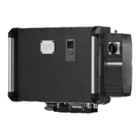
Device overview
Manual – EtherCAT
®
Interfaces, Field Distributors
20
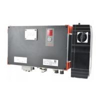
4.3.4 Field distributor ..Z.8.
X2
X11
X3
X12
X13
X15
X14
X16
[1]
[2][3]
[4]
[5]
[6]
[7]
[8]
[9]
[10]
18014399645961355
[1] Cable gland 6 × M20 × 1.5 (2 EMC cable glands included in the delivery). For
DeviceNet™: Micro-style connector/M12 connector (X11)
[2] 2 × M25 × 1.5 cable glands
[3] Terminals for power supply and PE connection (X1)
[4] Maintenance switch "Maintenance switch"(→220)
[5] MOVIMOT
®
inverter
[6] Terminals for bus, sensor, actuator, 24 V connection (X20)
[7] Pluggable terminal "Safety Power" for 24 V MOVIMOT
®
supply (X40)
[8] Terminal block for 24 V through-wiring (X29), internal connection to 24 V on
X20
[9] Hybrid cable connection; connection to AC motor (X9)
[10] Connection PE/equipotential bonding
4.3.5 Maintenance switch
The maintenance switch with line protection can be secured with 3 locks.
For the designs MFZ26J, MFPZ28J, and MFZ29J, the maintenance switch offers an
integrated feedback option for the current position. Feedback is evaluated by the DI0
binary input. For further information, refer to the chapter "Connecting MFE72 fieldbus
interface inputs/outputs"(→252).
The following figure shows the maintenance switch:
I
O
N
I
O
N
0 OFF
0 OFF
Ø 5 – Ø 8 mm
1136352395
25809148/EN – 01/2019

 Loading...


