11
Supplementary field distributor startup information
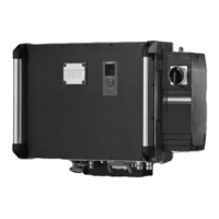
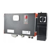
MF../MM../Z.8. field distributor
Manual – EtherCAT
®
Interfaces, Field Distributors
87
11.2.2 Internal wiring of the MOVIMOT
®
inverter in the field distributor
24V
TH
L
R
1
2
3
4
5
6
7
8
PE
L1
L1
L2
L2
L3
L3
PE
TH
[1]
[2]
[3]
X4
X6
X1
13
15
ϑ
9007200441652619
[1] DIP switches for setting the connection type (W or m)
Make sure that the connection type of the connected motor corresponds
with the setting of the DIP switch.
[2] Note the enabled direction of rotation
(Both directions of rotation are enabled as standard)
Both directions of rota-
tion are enabled
Only CCW direction of
rotation is enabled
Only CW direction of rotation is
enabled
24V
TH
L
R
24V
TH
L
R
24V
TH
L
R
TH
TH
TH
ϑ
ϑ ϑ
[3] Connection for internal braking resistor (in motors without brake only)
11.3 MF../MM../Z.8. field distributor
11.3.1 Maintenance switch
The maintenance switch of the Z.8. field distributor switches the following supplies:
• Power supply and
• DC 24 V supply
WARNING
Electric shock caused by dangerous voltages in the connection box and field distrib-
utor.
The maintenance/miniature circuit breaker disconnects only the MOVIMOT
®
drive
from the power supply system, not the field distributor.
• Disconnect the inverter from the power. Observe the minimum switch-off time
after disconnection from the supply system:
– 1 minute
25809148/EN – 01/2019

 Loading...


