MOUNTING THE CONTROL BOX:
You have two options:
OPTION A: Set Top-Mounted
Secure the control box using the
velcro strips (#13) provided.
OPTION B: Flush-Mounted
Detach wall plate from control box case.
Cut hole in wall large enough to accom-
modate the cable connections. Pull cables and
power wires through wall.
CONNECTING CONTROL BOX
Connections on the back of the control box are clearly
marked.
WARNING
DO NOT CONNECT TO BOAT’S AC OR DC POWER
SUPPLY until all other connections on the control
box are completed.
1. The 5 ft.18 GA power wire (#7) provided has a + (red)
wire and - (black) wire. Crimp ring terminals (#11) on
one end of power wire. Connect two insulated quick-
disconnect terminals (#12) to other end. Connect the
end with the quick-disconnect terminals to the back of
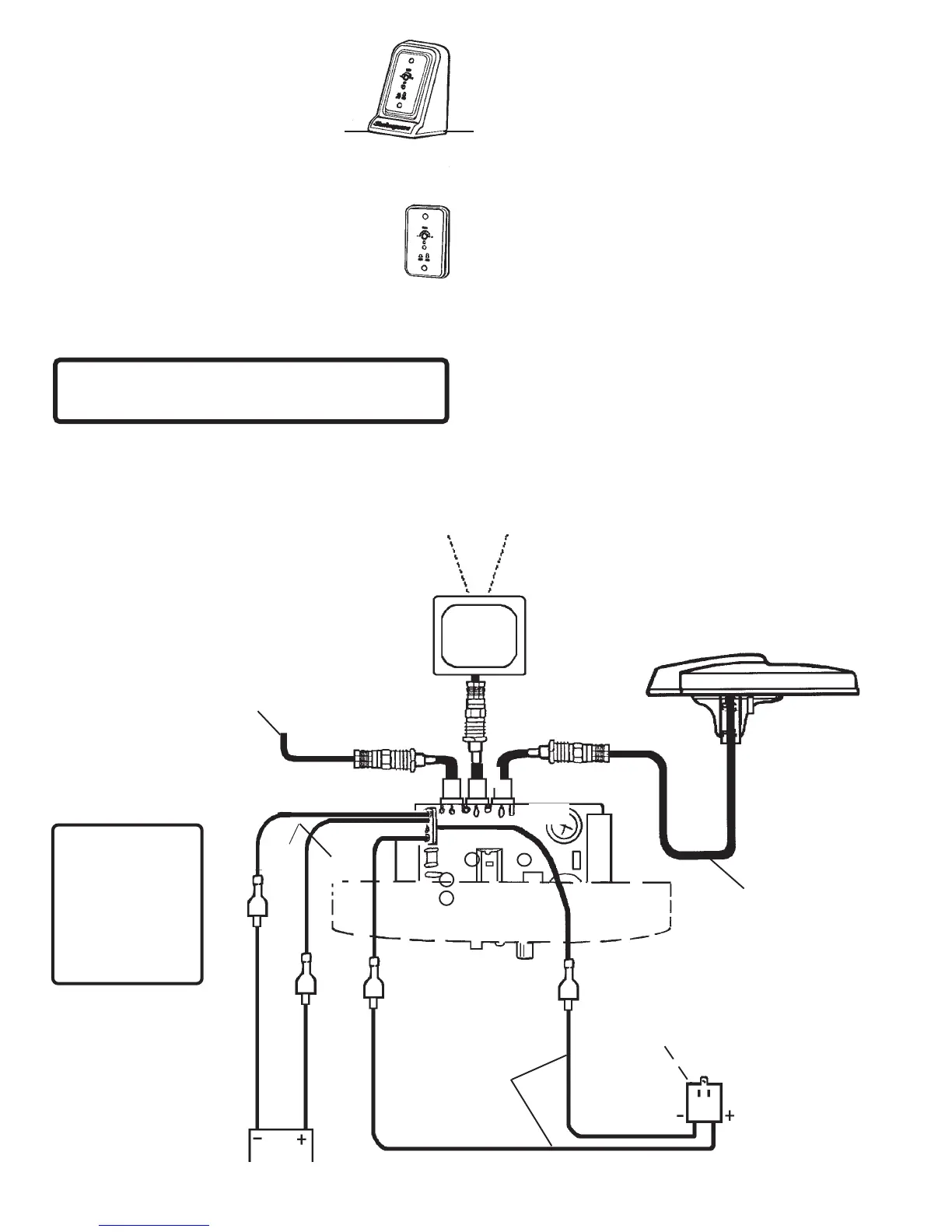
the control box, EXACTLY AS SHOWN in Figure 5.
Connect the end with the ring terminals to the appro-
priate + (red) and - (black) terminals on the 117 VAC
plug-in transformer (#6), Figure 5.
RED
BOAT BATTERY
12-24 vDC
PLUG-IN
TRANSFORMER
18 GA WIRE
(not provided)
18 GA WIRE
(5 ft. provided)
RG-59 COAX
CABLE
(30 ft. provided)
FROM SHORE CABLE
TV ON VCR AUXILIARY
COAXIAL CABLE
(not provided)
BLACK
2. There are three coax cable connections on the back of
the control box — Antenna, TV Set and Auxiliary (for
cable, VCR, satellite, etc.). Attach cable from antenna
to the antenna connector on the control panel. If an
auxiliary source will be used, connect it now. Connect
the TV cable to the back of the control panel. See
Figure 5 for correct connections.
3. To connect a 12-24 vDC power source to the back of
the control box, install two (#12) quick disconnect
terminals on an 18-ga. insulated wire (not provided).
Be sure to observe correct polarity when making
these connections. See Figure 5.
NOTE: Power switches automatically between 117
volts AC (wall power source) and 12-24 volts DC (boat
battery) as needed.
4. Plug transformer into AC receptacle. Use the
receptacle cover plate screw to secure the trans-
former to the AC receptacle.
5. For antenna reception, push in the On/Off button
on the front of the control panel. The Red LED will light
on the control panel and on the bottom of the antenna.
For auxiliary reception, the button should be out.
No red light on control panel or antenna.
6. Turn on the TV. If you have a weak signal, turn the
gain knob on the front of the control panel
clockwise (up). If you have a strong signal, turn
counterclockwise (down). Use the least amount
of gain necessary for good reception.
3
FIGURE 5
RED
On/Off
Gain
Positive and
Negative leads
from Battery and
Transformer must
be connected to
the control box
terminals exactly
as shown
IMPORTANT
BLACK
 Loading...