MX3500N SIMULATION 7 – 20
9
9-2
Purpose
Operation test/check
Function (Purpose)
Used to check the operations of the sen-
sors and detectors in the duplex section
and its control circuit.
Section
Duplex
Item
Operation
Operation/Procedure
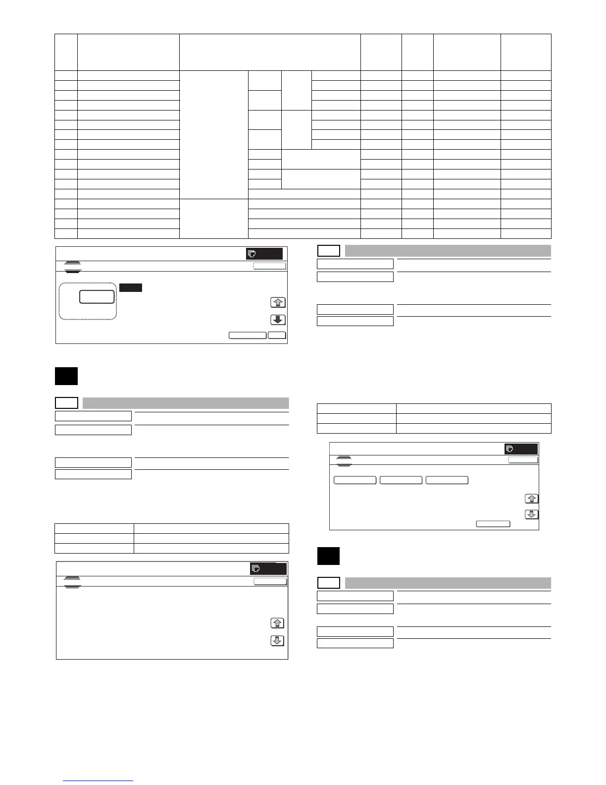
The sensor and detector operation conditions are displayed.
The active sensors and detectors are highlighted.
9-3
Purpose
Operation test/check
Function (Purpose)
Used to check the operations of the loads
in the duplex section and the control cir-
cuits.
Section
Duplex
Item
Operation
Operation/Procedure
1) Select the item to be operation tested with the buttons on the
touch panel.
2) Press [EXECUTE] button.
The selected load operation is performed.
When [EXECUTE] button is pressed, the output is terminated.
10
10-1
Purpose
Operation test/check
Function (Purpose)
Used to check the operations of the toner
motor and the related circuit.
Section
Process (Developing)
Item
Operation
Operation/Procedure
* Before execution of this simulation, remove the toner cartridges.
1) Select the item to be checked with the buttons on the touch
panel.
2) Press [EXECUTE] button.
* The selected load operation is performed for 10 sec.
* When [EXECUTE] button is pressed, the operation is termi-
nated.
H TC2 PLAIN CL SPX Secondary transfer
bias reference
value
COLOR Normal
paper
Front surface 51 to 255 136 2µA to 45µA20µA
I TC2 PLAIN CL DPX Back surface 51 to 255 136 2µA to 45µA20µA
J TC2 PLAIN BW SPX BLACK Front surface 51 to 255 117 2µA to 45µA16µA
K TC2 PLAIN BW DPX Back surface 51 to 255 117 2µA to 45µA16µA
L TC2 HEAVY CL SPX COLOR Heavy
paper
Front surface 51 to 255 79 2µA to 45µA8µA
M TC2 HEAVY CL DPX Back surface 51 to 255 70 2µA to 45µA6µA
N TC2 HEAVY BW SPX BLACK Front surface 51 to 255 79 2µA to 45µA8µA
O TC2 HEAVY BW DPX Back surface 51 to 255 70 2µA to 45µA6µA
P TC2 OHP CL COLOR OHP 51 to 255 65 5µA to 45µA5µA
Q TC2 OHP BW BLACK 51 to 255 65 5µA to 45µA5µA
R TC2 ENVELOPE CL COLOR Envelope 51 to 255 184 5µA to 45µA30µA
S TC2 ENVELOPE BW BLACK 51 to 255 184 5µA to 45µA30µA
T TC2 CLEANING Cleaning process 51 to 255 79 5µA to 45µA8µA
U TC2 CLEAN LOW SPD Secondary transfer
cleaning bias
reference value
Low speed print 51 to 255 72 –50V to –1500V –200V
V TC2 CLEAN MIDDLE SPD Middle speed print 51 to 255 100 –50V to –1500V –400V
W TC2 CLEAN HIGH SPD High speed print 51 to 255 114 –50V to –1500V –500V
X TC2 CLEAN CLEANING Cleaning 51 to 255 156 –50V to –1500V –800V
Item Display Content
Setting
range
Default
value
Actual output
setting range
Default
value
Actual
output value
DSW_ADU ADU transport open/close detection
APPD1 ADU transport path detection 1
APPD2 ADU transport path detection 2
CLOSE
A:
A : 232
B : 232
C: 139
TC1 LOW SPEED
CL
K
TC1 MIDDLE SPEED
CL
K
TC1 LOW SPEED
CL
CMY
SIMULATION
NO.08-06
THV S E TTING AND OUTPUT
232
[ 0~255]
OK
TEST
EXECUTE
0
D : 139
TC1 MIDDLE SPEED CL
CMY
CLOSE
0
ADU SENSOR CHECK
1/1
CLOSE
SIMULATION
NO.09
㧙
02
TEST
1/1
DSW_ADU
APPD1 APPD2
ADUM_L ADU motor lower
ADUM_U ADU motor upper
ADUGS ADU gate solenoid
0
SIMULATION
NO.09-03
TEST
ADU LOAD CHECK
EXECUTE
1/1
ADUM_L
ADUM_U
ADUGS
CLOSE
 Loading...