MX3500N SIMULATION 7 – 143
3) When [OK], [↑], [↓] button, [COLOR], or [BLACK] key is
pressed, the current entered value is saved to EEPROM and
RAM.
<Set range and default value of each setup>
67-33
Purpose
Adjustment
Function (Purpose)
Used to execute the gamma correction
between printer screens. (for PCL)
Section
Printer
Item
Adjustment
Operation/Procedure
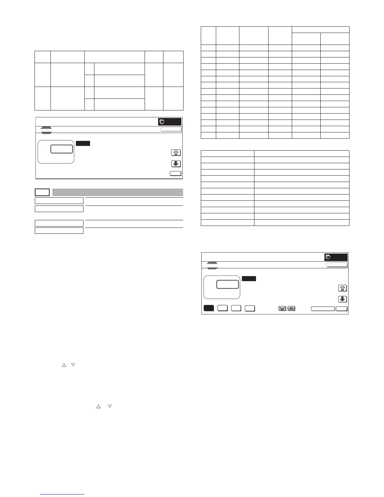
1) Use [K][C][M][Y] buttons to select a color. (The selected color
button is highlighted.)
Use [SCREEN] button to select a screen. (In this example,
SCREEN2 is selected.)
Select the set item with [↑] and [↓] buttons.
The highlighted set value is switched and the value is dis-
played in the setting area.
* If there is any item over [↑], an active display is made and
item is shifted.
If there is no item over [↑], the display grays out and the
operation is invalid.
If there is any item under [↓], an active display is made and
item is shifted.
If there is no item over [↓], the display grays out and the
operation is invalid.
2) Enter the set value with 10-key.
* Press [C] key to clear the entered values.
* Use [ ] [ ] buttons to change the set values collectively.
When the set value is not the upper limit (lower limit) value,
the value is increased (decreased) by 1. If the set value is
the upper limit (lower limit) value, it is not changed.
3) When [OK] button is pressed, the current set data are saved to
EEPROM and RAM.
* Also when [↑], [↓], [ ], [ ] button, or [COLOR], [BLACK]
key is pressed, the value is saved to EEPROM and RAM.
<Set range and default value of each setup>
<Selectable items on the screen>
(*): When SCREEN6/SCREEN7/SCREEN10/SCREEN11 is dis-
played, [K] data only. When [C] [M] [Y] button is pressed, the gray-
out keys are disabled.
Item Display Content
Set
range
Default
value
A SCREEN
(0:YES 1:NO)
0 Change of screen for
each object is allowed.
0 to 1 0
(YES)
1 Change of screen for
each object is inhibited.
BCOLOR
(0:YES 1:NO)
0 Change of color for
each object is allowed.
0 to 1 0
(YES)
1 Change of color for
each object is inhibited.
0
A:
A:0
B:0
SCREEN(0:YES 1:NO)
COLOR(0:YES 1:NO)
SIMULATION NO.67-32
MODE
0
㨇 0㨪 1 㨉
OK
TEST
CLOSE
Item Display Description
Set
range
Default value
SCREEN1
– 9 (KCMY)
SCREEN10
, 11 (K)
A POINT1 Point 1 0 to 255 128 127
B POINT2 Point 2 0 to 255 128 125
C POINT3 Point 3 0 to 255 128 124
D POINT4 Point 4 0 to 255 128 124
E POINT5 Point 5 0 to 255 128 122
F POINT6 Point 6 0 to 255 128 120
G POINT7 Point 7 0 to 255 128 114
H POINT8 Point 8 0 to 255 128 105
I POINT9 Point 9 0 to 255 128 95
J POINT10 Point 10 0 to 255 128 82
K POINT11 Point 11 0 to 255 128 70
L POINT12 Point 12 0 to 255 128 64
M POINT13 Point 13 0 to 255 128 57
N POINT14 Point 14 0 to 255 128 62
O POINT15 Point 15 0 to 255 128 75
Display Content
SCREEN1 4bit_LOW (Photo)
SCREEN2 4bit_HIGH (Graphic)
SCREEN3 1bit_LOW (Photo)
SCREEN4 1bit_HIGH (Graphic)
SCREEN5 4bit_CAD
SCREEN6 Mono (600 x 600) (*)
SCREEN7 Mono (1200 x 600) (*)
SCREEN8 Toner save 1bit_LOW (Photo)
SCREEN9 Toner save 1bit_HIGH (Graphic)
SCREEN10 Toner save Mono (600 x 600) (*)
SCREEN11 Toner save Mono (1200 x 600) (*)
0
A:
A㧦128
B㧦128
C㧦128
; POINT1
; POINT2
; POINT3
SIMULATION NO.67-33
PRINTER SCREEN GAMMA ADJUSTMENT(SCREEN 1)
128
㨇 0 㨪 255㨉
OK
TEST
K
C
M
Y
CLOSE
SCREEN
D㧦128 ; POINT4
 Loading...