MX3500N ADJUSTMENTS 6 – 8
ADJ 5 Image density sensor, image
registration sensor adjustment
There are some assembly variations in the image density sensor
section. Therefore, the absolute detection level differs in each
machine. To correct this, calibration is executed.
This adjustment must be executed in the following cases:
* When the image density sensor is replaced.
* When the image resist sensor is replaced.
* When U2 trouble occurs.
* When the PCU PWB is replaced.
* When EEPROM on the PCU PWB is replaced.
The targets of the adjustment are the color image density sensor,
the black image density sensor, and the image registration sensor.
There are following adjustment methods.
* Color image density sensor adjustment (Calibration with the
adjustment jig) SIM44-13
* Black image density sensor and the image registration sensor
adjustment SIM44-2
NOTE: Before executing this adjustment, check to confirm the fol-
lowing items.
* Check to confirm that the color image density sensor, the black
image density sensor, and the image registration sensor are
clean.
* Check to confirm that the image density sensor calibration plate
is clean.
* Check to confirm that the transfer belt is clean and free from
scratches.
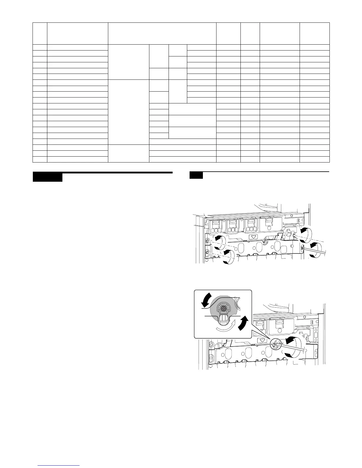
5-A Color image density sensor calibration
1) Open the front cabinet of the main unit, and remove the waste
toner box.
2) Remove the primary transfer unit fixing screw.
3) Turn to the transfer belt tension release cam and release the
primary transfer belt tension.
NOTE: When the transfer belt tension of the primary transfer
unit is released manually, turn on the power again after com-
pletion of the work. (Power OFF-ON) This procedure initializes
the transfer roller to return it to the home position.
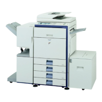
Item Display Content
Setting
range
Default
value
Actual output
setting range
Default
value
Actual
output value
A TC1 LOW SPEED CL K Primary transfer
bias reference
value
COLOR K Low speed 0 to 255 232 –500V to 5000V 4500V
B TC1 MIDDLE SPEED CL K Middle speed 0 to 255 232 –500V to 5000V 4500V
C TC1 LOW SPEED CL CMY CMY Low speed 0 to 255 139 –500V to 5000V 2500V
D TC1 MIDDLE SPEED CL CMY Middle speed 0 to 255 139 –500V to 5000V 2500V
E TC1 LOW SPEED BW K BLACK K Low speed 0 to 255 232 –500V to 5000V 4500V
F TC1 MIDDLE SPEED BW K Middle speed 0 to 255 232 –500V to 5000V 4500V
G TC2 PLAIN CL SPX Secondary transfer
bias reference
value
COLOR Normal
paper
Front surface 51 to 255 100 2µA to 45µA12.5µA
H TC2 PLAIN CL DPX Back surface 51 to 255 100 2µA to 45µA12.5µA
I TC2 PLAIN BW SPX BLACK Front surface 51 to 255 90 2µA to 45µA10µA
J TC2 PLAIN BW DPX Back surface 51 to 255 90 2µA to 45µA10µA
K TC2 HEAVY1 CL SPX COLOR Heavy paper 51 to 255 69 2µA to 45µA6µA
L TC2 HEAVY1 BW SPX BLACK 51 to 255 69 2µA to 45µA6µA
M TC2 OHP CL COLOR OHP 51 to 255 60 2µA to 45µA4µA
N TC2 OHP BW BLACK 51 to 255 60 2µA to 45µA4µA
O TC2 ENVELOPE CL COLOR Envelope 51 to 255 184 2µA to 45µA30µA
P TC2 ENVELOPE BW BLACK 51 to 255 184 2µA to 45µA30µA
Q TC2 CLEANING Cleaning process 51 to 255 79 2µA to 45µA8µA
R TC2 CLEAN LOW SPD Secondary transfer
cleaning bias
reference value
Low speed print 51 to 255 72 –50V to –1500 –200V
S TC2 CLEAN MIDDLE SPD Middle speed print 51 to 255 72 –50V to –1500V –200V
T TC2 CLEAN CLEANING Cleaning 51 to 255 156 –50V to –1500V –800V
UN LOCK
 Loading...