MX3500N ADJUSTMENTS 6 – 31
18-B Copy image position, image loss
adjustment (RSPF mode)
(Refer to the MX-RPX1 SM.)
ADJ 19 Print lead edge image position
adjustment (Printer mode)
(Print engine section)
This adjustment is required in the following cases:
* When the resist roller section is disassembled.
* When the LSU is replaced or removed.
* When a U2 trouble occurs.
* When the PCU PWB is replaced.
* When the EEPROM on the PCU PWB is replaced.
(Caution)
This adjustment is performed by the user to increase the lead edge
void area to greater than the standard value (3mm) in the printer
mode.
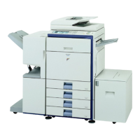
1) Enter the simulation 50-05 mode.
2) Select the set item E with the scroll key, and enter the value
corresponding to the paper feed tray with A4 (11 x 8.5) paper
in it.
3) Press [EXECUTE] key.
The adjustment pattern is printed.
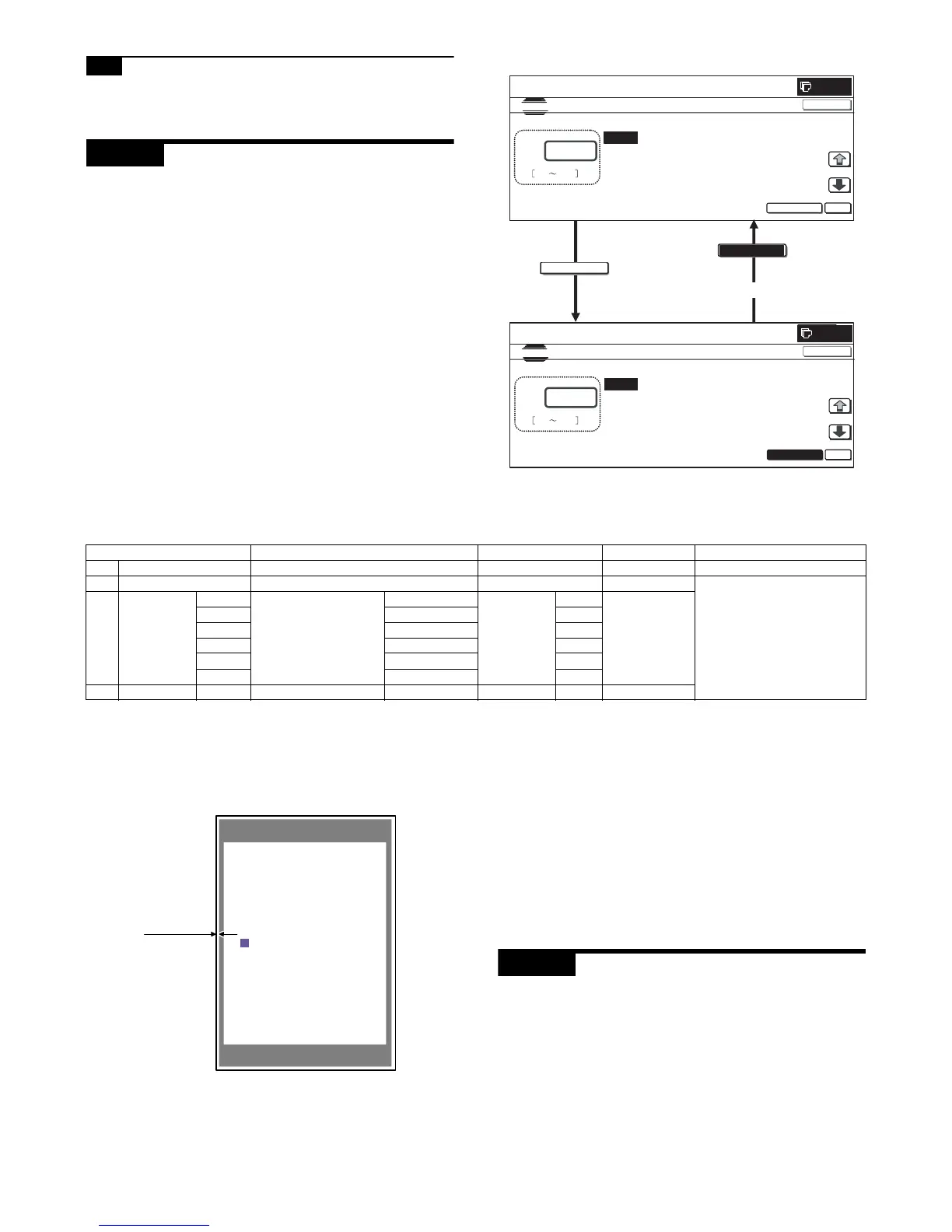
4) Measure the distance from the paper lead edge the adjustment
pattern to the image lead edge, and check to confirm that it is
in the standard adjustment value range.
Standard adjustment value: 3.0 ± 2.0mm
If the above condition is not satisfied, perform the following
procedures.
5) Select the adjustment target of the paper feed mode adjust-
ment item DENC with the scroll key.
6) Change the adjustment value.
Enter the adjustment value and press [OK] or [EXECUTE] key.
When [EXECUTE] key is pressed, the adjustment pattern is
printed.
When the adjustment value is increased, the distance from the
paper lead edge to the image lead edge is increased. When
the adjustment value is decreased, the distanced is
decreased.
When the set value is changed by 1, the distance is changed
by about 0.1mm.
Repeat the procedures 4) – 6) until the condition of 4) is satisfied.
ADJ 20 Copy color balance/density
adjustment
(1) Note before execution of the copy color balance/density
adjustment
* After completion of this adjustment, the printer color balance/
density adjustment must be executed.
* Requisite conditions before execution of the copy color balance/
density adjustment
Before execution of the copy color balance/density adjustment,
check to insure that the adjustments which affect the copy color
balance/density adjustment have been completed.
The importance levels of them are shown below.
EXECUTE
EXECUTE
0
 Loading...