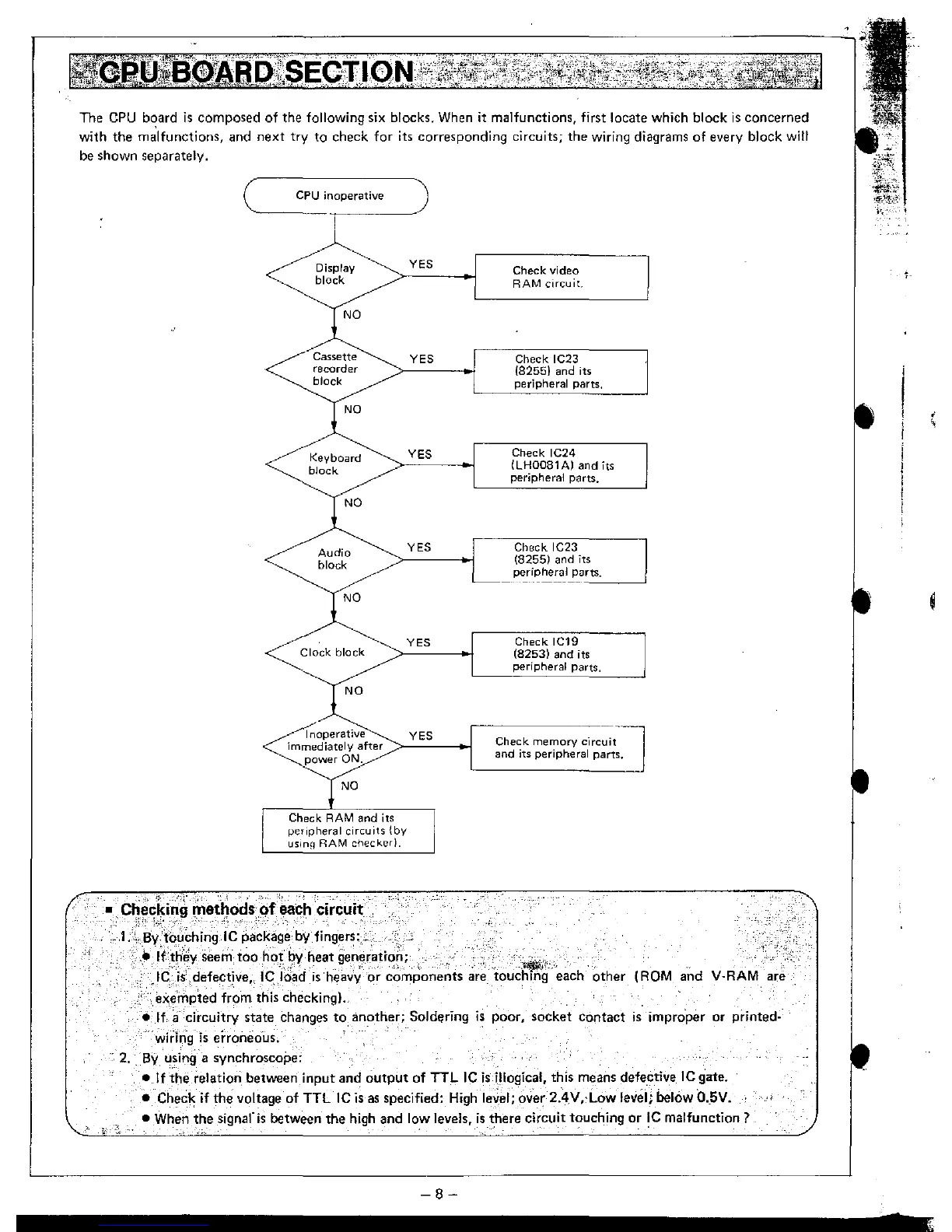
The
CPU
b~ard
is
composed of the following six blocks.
When
it malfunctions, first locate which block
is
concerned
with the
malfunctions, and next try to check for its corresponding circuits; the wiring diagrams of every block will
be
shown separately.
CPU
inoperative
Display
block
Cassette
recorder
block
Keyboard
block
Audio
block
NO
Clock
block
NO
YES
YES
YES
YES
YES
<e
noperative
YES
immediately
after
>------0-1
power
ON,
NO
Check
RAM
and its
peripheral
circuits
{by
usinfj
RAM
checked,
Check
video
RAM
circuit.
Check IC23
(8255)
and its
peripheral parts,
Check
IC24
(LH0081A)
and
its
peripheral parts.
Check
IC23
(8255)
and
its
peripheral
P<lrts.
----'
Check
IC19
(8253)
and its
peripheral parts,
Check
memory
circuit
and
its
peripheral parts,
•
Checki~g
rnetl1ods()f~~h
circuit
-,,;
"I,
","
..
,,,'
"_
•
",.
'"
_
:.l.C.By .tbuChinglC package
by
fingers:c .
.•.
Ifthey
seem too
hot
by
heat
gene~atiori;
2.
I(:::--j{ defective" le
'Idad
'is
'hea~'y
'or
~'~mporients
are
~ouc~~-
'"each'
other
(ROM
and V·RAM are
.
ex.~mpted
f;~m
this checking).
e,
If.-
a circuitry state changes to,
an~ther;
Sold~ring
is-
poor, socket contact
is
impro'per or printed-
wiring
is
erroneous.
By
using a synchroscope:
•
If
the
relation between input and
output
of TTL
IC
is
illogical, this means defe.etive
IC
gate.
•
Check if the voltage of TTL
IC
is
as
specified: Highle,;el; over 2.4V"Low level; below O
..
5V.
• When the signal'is between the high and low levels,
is
~here
circuit t?uching or
!C
malfunction?
-8-
,
,