R-15AM
17
Pin No. Signal I/O Description
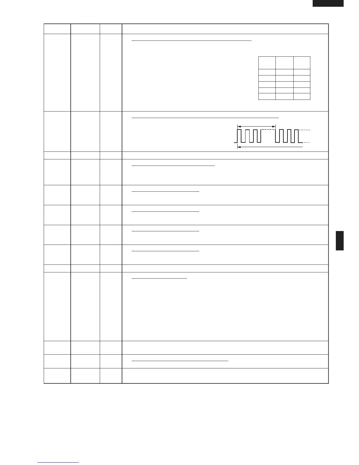
29 R42 OUT Magnetron high-voltage circuit driving signal.
To turn on and off the cook relay (RY3).
In 100% POWER operation, the signals
hold "L" level during microwave cooking
and "H" level while not cooking. In other
cooking modes (70%, 50%, 30%, 10%)
the signal turns to "H" level and "L" level
in repetition according to the power
level.
30 R43 OUT Oven lamp, fan motor and antenna motor driving signal.
To turn on and off shut off relay (RY1). The
square waveform voltage is delivered to
the RY1 driving circuit.
31-33 R50-R52 OUT Terminal not used.
34 R53 IN Signal coming from tact switch.
When either of tact switches SW60-SW63 is touched, a corresponding signal
out of R60, R61, R62 and R63 will be input into R53. When no key is touched,
the signal is held at "H" level.
35 R60 OUT Tact switch strobe signal.
Signal applied to tact switch section. A pulse signal is input to R53 terminal
while the tact switch SW60 is touched.
36 R61 OUT Tact switch strobe signal.
Signal applied to tact switch section. A pulse signal is input to R53 terminal
while the tact switch SW61 is touched.
37 R62 OUT Tact switch strobe signal.
Signal applied to tact switch section. A pulse signal is input to R53 terminal
while the tact switch SW62 is touched.
38 R63 OUT Tact switch strobe signal.
Signal applied to tact switch section. A pulse signal is input to R53 terminal
while the tact switch SW63 is touched.
39-42 R70-R73 OUT Terminal not used.
43-54 SEG0 - OUT Segment data signal.
SEG11 Connected to LCD.
The relation between signals are as follows:
LSI signal (Pin No.) LCD segment LSI signal (Pin No.) LCD segment
SEG 0 (43) ............................ S12 SEG 6 (49) ............................ S6
SEG 1 (44) ............................ S11 SEG 7 (50) ............................ S5
SEG 2 (45) ............................ S10 SEG 8 (51) ............................ S4
SEG 3 (46) .............................. S9 SEG 9 (52) ............................ S3
SEG 4 (47) .............................. S8 SEG 10 (53) .......................... S2
SEG 5 (48) .............................. S7 SEG 11 (54) .......................... S1
55-57 SEG12- OUT Terminal not used.
SEG14
58 VDD IN Power source voltage input terminal.
Connected to GND.
59-64 SEG15- OUT Terminal not used.
SEG20
ON/OFF time ratio in Mi-
cro cooking
(a. 32second time base)
MICRO ON OFF
COOK
100% 32sec. 0sec.
70% 24sec. 8sec.
50% 18sec. 14sec.
30% 12sec. 20sec.
10% 6sec. 26sec.
20.0 msec
During cooking
H : +5V
L : 0V