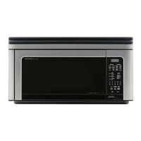
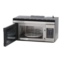
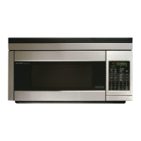
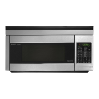
19
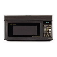
R-1850
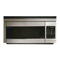
R-1851
TEST PROCEDURES
PROCEDURE
LETTER
COMPONENT TEST
When the power cord is plugged into the wall receptacle and 120 volts A.C. is supplied to the damper
motor, the motor operates until the damper is opened and the damper switch closes. Then the damper
motor stops operation.
If the damper motor does not operate, check for A.C. voltage with a voltmeter at the motor.
1. Disconnect the power cord from the wall receptacle.
2. Disconnect the wire leads of motor and connect the meter leads to the wire leads of main wire harness.
3. Re-connect the power cord into the wall receptacle.
If 120 volts A.C. is indicated at the wire leads, replace the motor and if 120 volts A.C. is not indicated,
check the wire harness and control unit.
N DAMPER MOTOR TEST
Make sure the heating element is fully cooled and test as follows;
a. Disconnect wire leads and measure the resistance with an ohmmeter. On the R x 1 scale, the
resistance between the heating element terminals should be approximately 10 Ω.
b. Disconnect wire leads and measure the insulation resistance with 500V - 100MΩ insulation
resistance meter. The insulation resistance between heating element terminal and cavity should be
more than 0.5MΩ.
O HEATING ELEMENT TEST
It is difficult to measure the exact temperature in the convection oven. An accurate thermocouple type
temperature tester must be used. A low priced bi-metal type thermometer is not reliable or accurate.
The temperature should be checked with outer case cabinet installed, approx. 5 minutes after preheat
temperature is reached (audible signal sounds four times). The temperature experienced may be
approx. 30˚F more or less than indicated on the display, however, in most cases the food cooking results
will be satisfactory. Difference in power supply voltage will also affect the oven temperature.
P CHECKING TEMPERATURE IN THE CONVECTION MODE
The touch control panel consists of circuits including semiconductors such as LSI, ICs, etc. Therefore,
unlike conventional microwave ovens, proper maintenance cannot be performed with only a voltmeter
and ohmmeter. In this service manual, the touch control panel assembly is divided into two units, Control
Unit and Key Unit, troubleshooting by unit replacement is described according to the symptoms
indicated.
1. Key Unit.
The following symptoms indicate a defective key unit. Replace the key unit.
a) When touching the pads, a certain pad produces no signal at all.
b) When touching a number pad, two figures or more are displayed.
c) When touching the pads, sometimes a pad produces no signal.
2. Control Unit.
The following symptoms indicate a defective control unit. Replace the control unit.
2-1 Programming problems.
a) When touching the pads, a certain group of pads do not produce a signal.
2-2 Display problems.
a) For a certain digit, all or some segments do not light up.
b) For a certain digit, brightness is low.
c) Only one indicator does not light.
d) The corresponding segments of all digits do not light up; or they continue to light up.
e) Wrong figure appears.
f) A certain group of indicators do not light up.
g) The figure of all digits flicker.
2-3 Other possible problems caused by defective control unit.
a) Buzzer does not sound or continues to sound.
b) Clock does not operate properly.
c) Cooking is not possible.
d) Proper temperature measurement is not obtained.
Q TOUCH CONTROL PANEL ASSEMBLY TEST