R -6280
TEST PROCEDURES (CONT’D)
PROCEDURE
LETTER
COMPONENT TEST
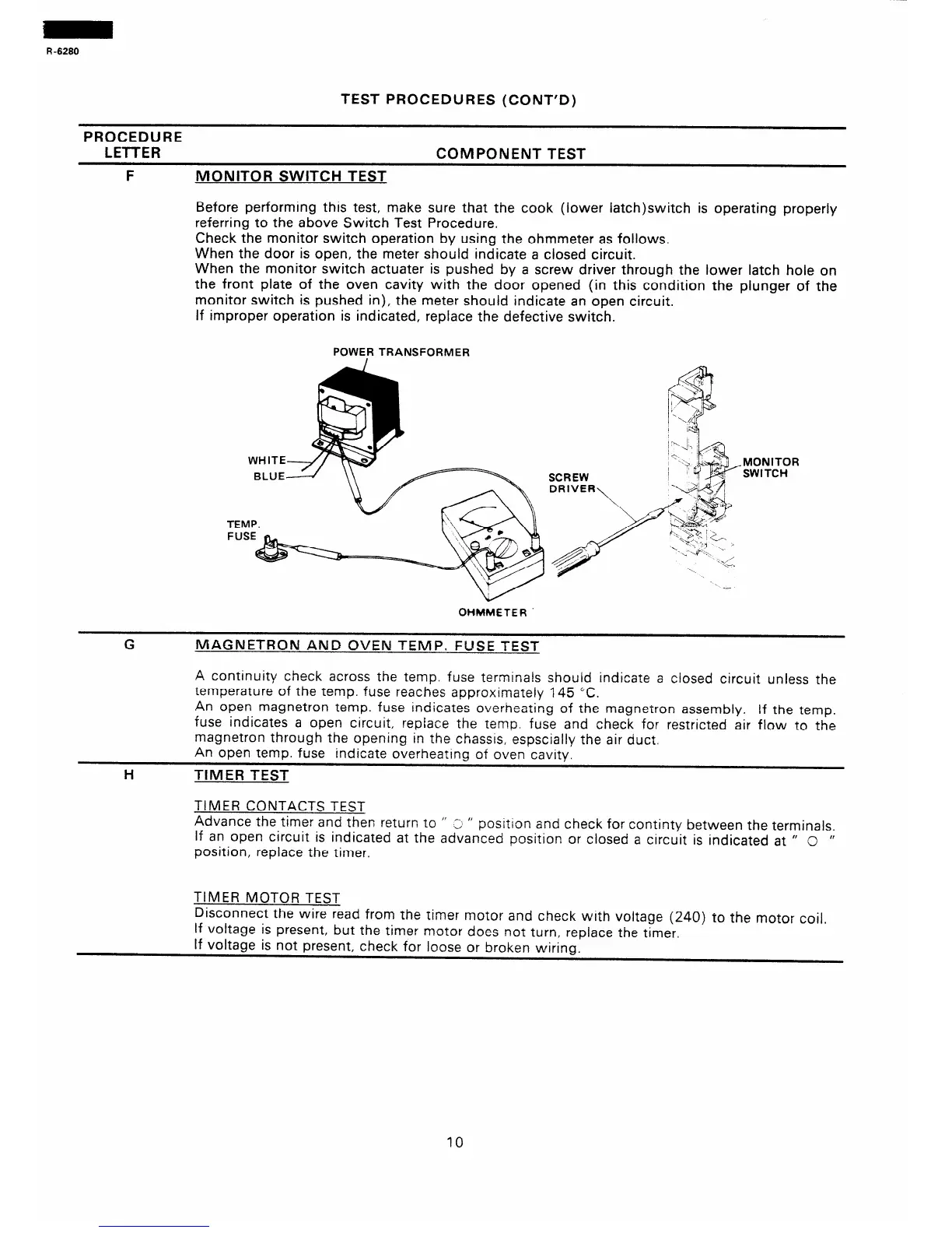
F MONITOR SWITCH TEST
Before performing this test, make sure that the cook (lower iatch)switch is operating properly
referring to the above Switch Test Procedure.
Check the monitor switch operation by using the ohmmeter as follows.
When the door is open, the meter should indicate a closed circuit.
When the monitor switch actuater is pushed by a screw driver through the lower latch hole on
the front plate of the oven cavity with the door opened (in this condition the plunger of the
monitor switch is pushed in), the meter should indicate an open circuit.
if improper operation is indicated, replace the defective switch.
POWER TRANSFORMER
TEMP.
OHMMETER
.-
MONITOR
SWITCH
G
MAGNETRON AND OVEN TEMP. FUSE TEST
A continuity check across the temp. fuse terminals should indicate a closed circuit unless the
temperature of the temp. fuse reaches approximateiy 145 “C.
An open magnetron temp. fuse indicates overheating of the magnetron assembly. If the temp.
fuse indicates a open circuit, repface the temp. fuse and check for restricted air flow to the
magnetron through the opening in the chassis, espscially the air duct.
An open temp. fuse indicate overheating of oven cavity.
H
TIMER TEST
TIMER CONTACTS TEST
Advance the timer and then return to ” -, ”
positron and check for continty between the terminals
If an open circuit is indicated at the ad;anced position or closed a circuit is indicated at ” 0
”
position, replace the timer.
TIMER MOTOR TEST
Disconnect the wire read from the timer motor and check with voltage (240) to the motor coil.
If voltage is present, but the timer motor does not turn, replace the timer.
If voltage is not present, check for loose or broken wiring.
10