VIDEOICHROMA
ADJUSTMENT (Continued)
Adjusting Conditions
I
Adjusting Procedures
6.
PAL
Chroma
Adjustment
Adjusting Point
1.
Adjust the
Colour
control key so that the output
Cl
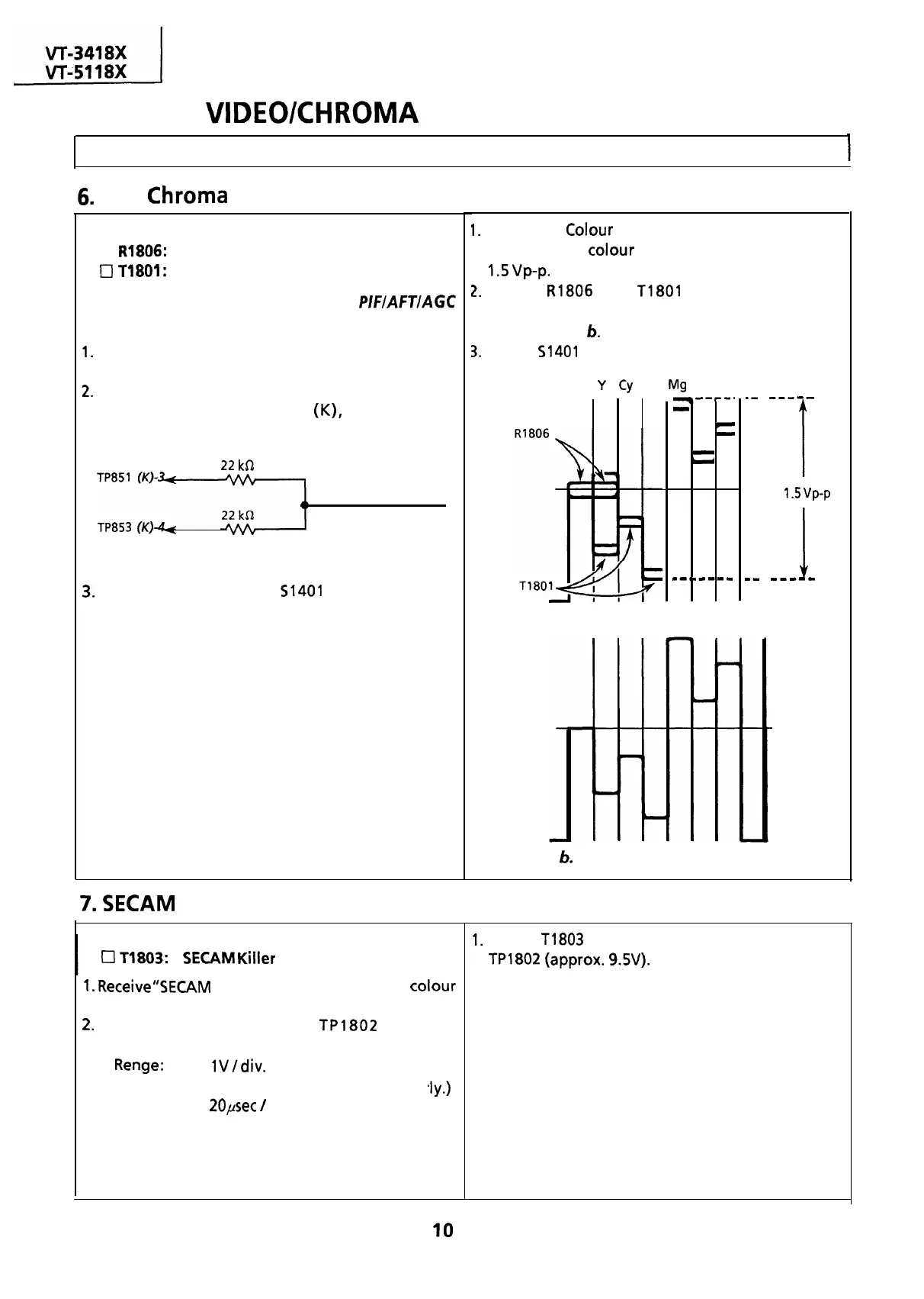
R1806:
1 H Delay Amp. control
waveform of
colour
difference signal becomes
0
T1801:
1 H Delay Phase control
1.5
vp-p.
Note: Before this adjustment, the
PIFIAFTIAGC
adjustment must have been completed.
1.
Receive “PAL COLOUR BAR” signal with pattern
generator.
2.
Connect the following resistance matrix to pins 3
and 4 of the connector
(K),
to which an
oscilloscope is connected.
22
kSZ
To oscilloscope
TP853
(K)+
Resistance Matrix
3.
Set the Service switch
51401
at the Video Cut
position to cut off the Y-signal.
7.
SECAM
Killer Adjustment
r
Adjusting Point
0
11803:
SECAM
Killer
control
1.
Receive”SECAM
COLOUR BAR” signal with
colour
bar generator.
2.
Connect oscilloscope to
TP1802
with the
,lY.)
following settings.
l
Renge:
lV/div.
DC
(Adjust vertical position proper
l
Sweep Time:
20psec
/
div.
2.
Adjust
R1806
and
T1801
so that the output
waveform shown in Fig. a is corrected to that
shown in Fig.
6.
3.
Return
51401
to CENTER (normal position).
W
Y
Cy
G Mg R B
--#--.
-
r
-
-
u
--*m---w
1
.-
---m-
1
1.5
vp-p
I
mm
--m-w
Figure a. Waveform before the adjustment
Figure
6.
Waveform after the adjustment
1.
Adjust
T1803
to obtain maximum DC voltage at
TPl802
(approx.
9.5V).
IO