VT-341
8X
VT-5118X
DEFLECTION LOOP ADJUSTMENT (Continued)
Adjusting Conditions
Adjusting Procedures
5.
Vertical Centering Adjustment
l
During
the’adjustment,
keep the unit facing the east.
Vertical Center Adjust switch
This adjustment should be performed after
the purity and convergence adjustments.
“MONOSCOPE PATTERN” signal.
1.
Adjust
5501
so that the picture’s vertical center is
idential to CRT geometrical vertical center.
ADJUSTMENT OF THE IF CIRCUIT
Adjustment of the RF
AGC
Adjustment of the AFT
Test point
TP201
@I
(GND)
TP201
0
(Video Output)
Adjusting point
I
VROOl
(AGC
control)
I
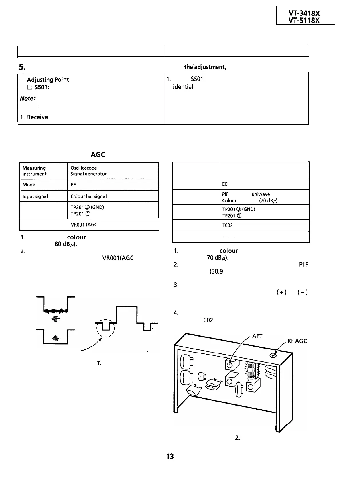
1.
Receive the
colour
bar signal (input field
strength:
80
dBp).
2.
Observe the video output terminal waveform
on the oscilloscope. Adjust
VROOl
(AGC
control)
in the IF pack until the noise disappears from
the oscilloscope screen and the waveform
nearly comes into sync.
Just before shrinking
Figure
1.
Measuring
Oscilloscope
instrument Signal generator
Mode
I
EE
Input signal
PIF
frequency
uniwave
Colour bar signal
(70
dBp)
Test point
I
TP201
@
(GND)
TP201
@
(Video Output)
Adjusting point
I
TOO2
(AFT coil)
Specification
-
I
1.
Receive the colour bar signal (input field
strength:
70
dBp).
2.
Using the signal generator, feed the
PIF
frequency
(38.9
MHz) signal (sinewave) to the
tuner IF output terminal.
3.
Set the tuning switch to the VHF or UHF
position. Keep the tuning button
(+)
or
(-)
depressed until the beating on the oscilloscope
screen be minimum.
4.
Set the tuning switch on the normal position.
Adjust
TOO2
(AFT coil) so that beating on the
oscilloscope screen be minimum.
I
Figure
2.
IF Pack
13
 Loading...

