VT-341
8X
W-5118X
REPLACEMENT OF A/C (Audio/Control)
HEAD
1.
Remove the cassette housing control assembly.
2.
Place the unit in the unloading mode, and
unplug the power cord.
l
Removal
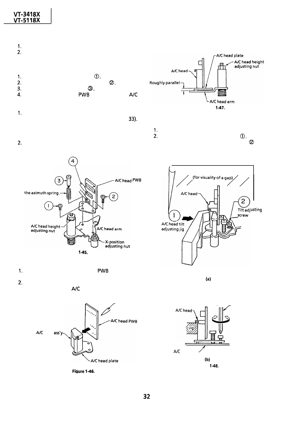
I.
Loosen the tilt adjusting screw
0.
2.
Remove the azimuth adjusting screw
Q.
3.
Remove the A/C head screw
0.
4.
Unsolder the A/C head
PWB
soldered to the
A/C
head assembly.
Notes:
1.
After replacement, be sure to perform the
adjustment of the tape drive train (see page
33).
Under any circumstances, avoid touching the
head. Clean the head, if touched with your
finger, with alcohol.
2.
Take care that the azimuth spring does not fly
off when removing the A/C head screw.
n
4
Pay attention to
PWB
Figure
l-45.
l
Replacement
1.
Solder the removed A/C head
PWB
onto a new
A/C head assembly.
2.
The A/C head assembly is attached so that the
A/C head arm and
A/C
head plate are roughly
parallel to each other.
/
Solder
LR
New
AK
head
ass’y
Never touch the head
Figure
l-47.
l
Adjustment
[A/C head tilt angle]
l_
Set the mechanism to the loading mode.
2.
Place the A/C head tilt adjusting Jig
0.
3 Slowly turn the tilt adjusting screw
Q
with a
screw driver until there is no gap between the Jig
and the A/C head.
h
A piece of white paper
1
usting
AK
head arm
f
Screw driver
b)
Figure 1-48.
Fiaure
146.
32