Chapter 3 Operating Instructions
ICR880/890 Camera Systems
26 © SICK AG · Germany · All rights reserved · Subject to change without notice 8011325/XL85/2013-08-20
Product description
3.4.2 Object trigger control
In order to initiate a reading process, the Camera System requires an appropriate signal
(trigger). The start signal is emitted via an external reading pulse sensor (photoelectric re-
flex switch) as standard. As soon as an object has passed the reading pulse sensor, an "in-
ternal reading gate" opens for the reading process.
Alternatively, a command activates the reading process via a data interface or the
CAN-SENSOR network.
The trigger source can be configured using the SOPAS-ET Configuration Software:
P
ROJECT TREE, ICR880/890, PARAMETER, READING CONFIGURATION, OBJECT TRIGGER CONTROL, reg-
ister tab S
TART/STOP OF OBJECT TRIGGER
3.4.3 Focus control
For dynamic focus control, the Camera requires continuous information on the distance to
the object surface. This data is provided by a lateral MLG Light Grid for readings from above.
The object dimensions are taken from the VMS4xx/5xx Volume Measurement System and
processed via the MSC800 for readings from the side.
The SOPAS-ET Configuration Software can, among other things, be used to configure fea-
tures, such as the default position and the source of the distance measurement:
P
ROJECT TREE, ICR880/890, PARAMETER, READING CONFIGURATION, FOCUS CONTROL, register tabs
O
PTIONS and DISTANCE MEASUREMENT SOURCE
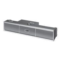
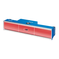
3.4.4 Illumination control
The area which is to be read must be illuminated with a high-performance LED illumination
when recording with the Camera. The ICI890 Illumination produces type-depended a thin
red illuminated area (= 620 nm) or a bluish white illuminated area (= 470 nm).
During reading from above, the light is deflected onto the conveyor system using the deflec-
tion mirror (Fig. 3-7, Page 27).
Fig. 3-6: Diagram of the illumination with illuminated area
 Loading...