12
MHS400 smart Installation and operating instructions
05.2017
7. Installation
7.1 Installation requirements
General information about installation
• The following description of the assembly process is a recommendation from SIEGENIA and describes the major steps
involved. The specific details of the assembly process are determined, amongst other factors, by the HS element used, by
the production process and by the window manufacturer's equipment and facilities.
• You will find specific steps for installation of the MHS400 smart on our download portal:
downloads.siegenia.com/de/00007/index.html
Tools required (not included in scope of delivery)
• Drill
• Ø 3 mm, Ø 7 mm, Ø 10 mm, Ø 15 mm timber or metal drill
• Phillips screwdriver (size 2)
• 1 screwdriver bit 90 mm long
• 2 screw clamps
• Folding rule
• Router (for timber elements)
• Between 2 and 4 assembly racks
• Recommendation: For straightforward and accurate positioning or fixing of the catch on the lift & slide sash,
SIEGENIA recommends using the catch jig (see accessories, page 53).
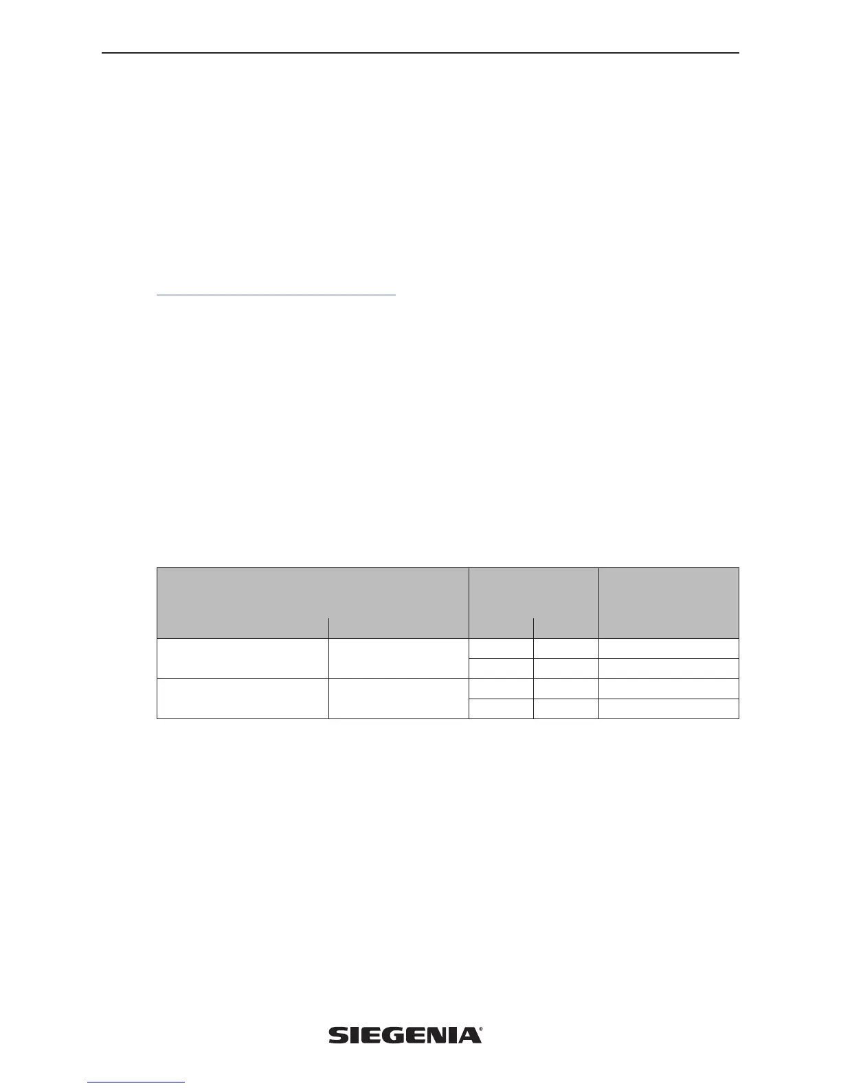
Materials required (not included in scope of delivery)
Screws
Number of units
(depending on RIB)*
Scheme
For component
For timber and PVC elements For aluminium elements A C
Screw
PC 4.1 x 38 mm
Flow-drill screw
M4 x 18 mm
10–25 20–50 Slide drive SA*
2 4 Catch
Screw
PC 4.1 x 19 mm
Flow-drill screw
M4 x 18 mm
4–6 8–12 Fixing plate HA
6 12 Cable holder
Note: All screwing points must be pre-drilled to Ø 3 mm. The length of the fixing screws for PVC elements must be
sufficient to penetrate deep enough into the reinforcing material to ensure a sufficient hold. Materials for lining the slide
drive SA (PVC plates, for example) must be provided by the customer for certain lift & slide profile systems.
 Loading...