Chapter 4 – Troubleshooting
SEN0209R1
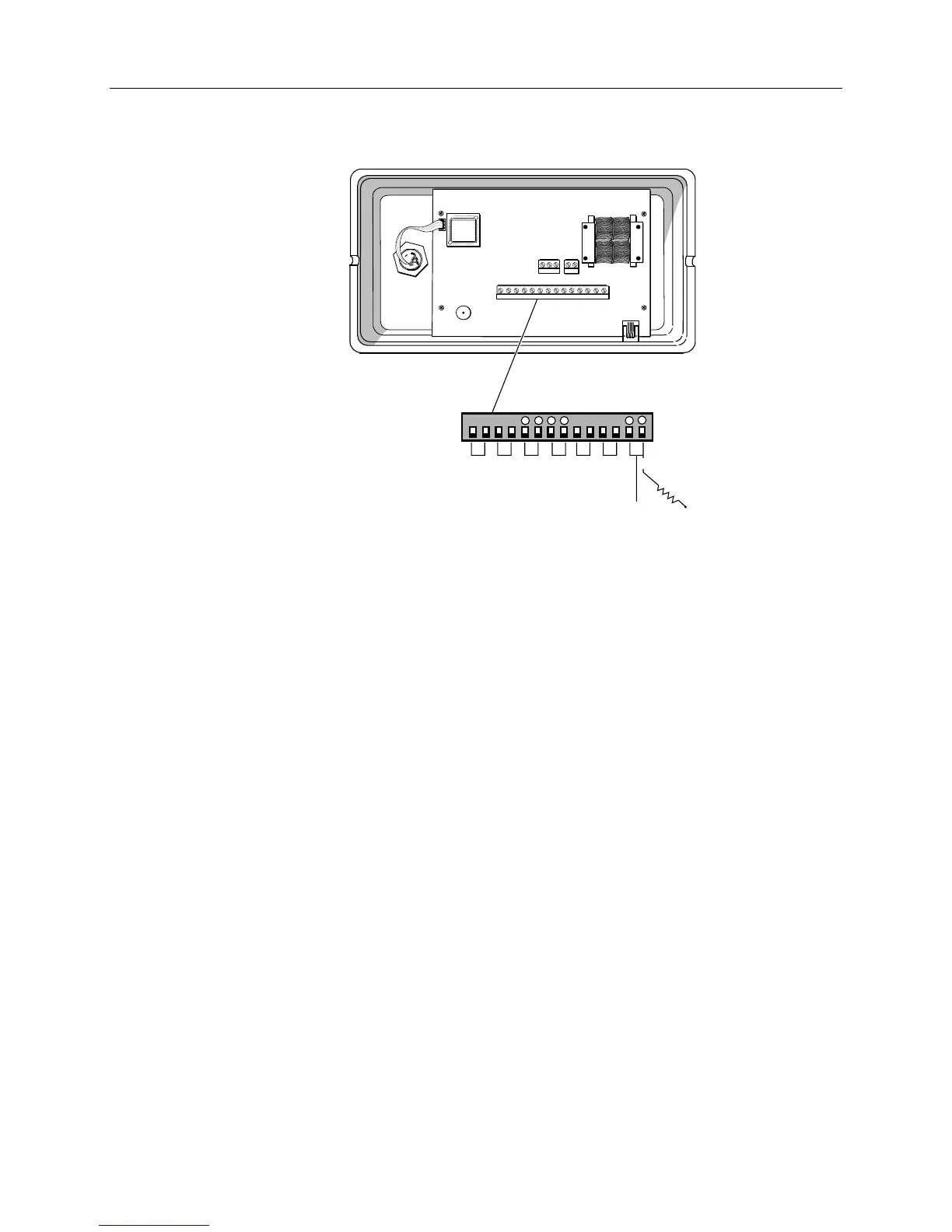
+
-
++
--
PIN# 1 2 3 4 5 6 7 8 9 10 11 12 13 14
500 Ω
4-20 mA
Signal
Figure 9. 4-20 mA Signal Output Point.
Troubleshooting
Find the symptom that best describes the problem. Perform the corrective action that follows.
If the problem persists, contact your local Siemens Building Technologies representative.
A. DP1 FAIL (Point 16) reads ON at the POT and GENERAL FAILURE is
displayed on the LCD.
– or –
DP2 FAIL (Point 17) reads ON at the POT and
GENERAL FAILURE is
displayed on the LCD.
1. Check the wire connections from the RPT to the monitor.
2. Check that the incoming 24 Vac power to the sensor is properly connected.
3. Contact your local Siemens Building Technologies representative.
B. The wire connections from the RPT sensor and the monitor are
correct, but the monitor is displaying
GENERAL FAILURE on the LCD.
1. Check that the correct application is running.
2. Contact your local Siemens Building Technologies representative.
Siemens Building Technologies, Inc. 31
 Loading...