Electrical Connections
2.2 Power connection
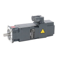
Table 2-1 Description of the diagram
No. Description No. Description
1 M5 connecting studs 5 M10 grounding studs
2 M10 connecting studs 6 M4 connecting studs
3 M4 grounding stud BR Brake connection
4 M6 grounding stud
Table 2-2 Connections for the terminal box
Terminal box
type
Cable gland Max. outer
cable
diameter
3)
[mm]
Max.
current
[A]
1)
Power
connection
Max.
cross-section
per phase
Ground
connection
Brake
connection
2)
gk130 1 x Pg29 30 36 3 x M4 1 x 6 mm
2
M4 1.5 mm
2
gk230 1 x Pg29 30 66 3 x M5 1 x 16 mm
2
M4 1.5 mm
2
gk420 1 x Pg36 37 104 4 x M10 1 x 35 mm
2
M6 1.5 mm
2
gk630 2 x M32 x 1.5 25 112 3 x M10 2 x 16 mm
2
M10 –––
gk630 2 x M40 x 1.5 32 176 3 x M10 2 x 35 mm
2
M10 –––
gk630 2 x M50 x 1.5 41 209 3 x M10 2 x 50 mm
2
M10 –––
1)
Data acc. to DIN EN 60204-1 (routing type C, ambient temperature 40° C)
2)
BR/BR2 (terminal strip, only for versions with brake)
3)
Dependent on the seal used
1FT6 synchronous motors
2-4 Configuration Manual, (PFT6), Edition 12.2004, 6SN1197-0AD12-0BP0
 Loading...


