Vacuum interrupter/
operator
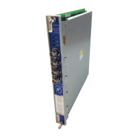
Figure 11: Type 38-3AH3 vacuum circuit breaker with inter-phase and outer-phase barriers
installed
20.0
40.0
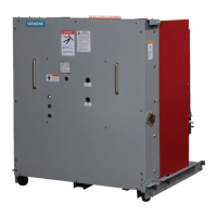
Figure 12: Interrupter/operating mechanism module (shown with outer-phase barrier removed)
16.0 - Insulator
20.0 - Pole head
29.0 - Lower connection terminal
30.0 - Vacuum interrupter
40.0 - Pole bottom
60.0 - Operator housing
60.0
16.0
30.0
29.0
The vacuum circuit breaker consists of two
sub-assemblies. The "interrupter/operator"
module is a unitized assembly of the three
vacuum interrupters, primary insulators
and operating mechanism. The second
module, the "vehicle", is the supporting
drawout-structure module for the
operating mechanism. The vehicle
provides primary-stud extensions, closed
circuit-breaker racking interlocks, closing
spring discharge feature and other
requirements needed to ensure safe and
reliable use during racking and during
operation. These two sub-assemblies will
be separately described.
Interrupter/operator module
The interrupter/operator module consists
of the three poles, each with its vacuum
interrupter and primary insulators,
mounted on the common motor or hand-
charged spring-stored energy-operating-
mechanism housing. This module is shown
in Figure 12: Interrupting/operating
mechanism module (shown with outer-
phase barrier removed).
Construction
Refer to Figure 12: Interrupting/operating
mechanism module (shown with outer-
phase barrier removed) on page 17, Figure
13: Operating mechanism controls and
indicators on page 18, Figure 14: Type 38-
3AH3 vacuum circuit breaker pole section
on page 19 and Figure 15: Stored-energy
operating mechanism on page 20.
Each of the circuit breaker poles is fixed to
the rear of the operating-mechanism
housing (60.0) by two cast-resin insulators
(16.0).
The insulators also connect to the upper
(20.0) and lower (40.0) pole-supports that
in turn support the ends of the vacuum
interrupter (30.0). Primary stud-extensions
are attached directly to the upper pole-
support (20.0) and lower terminal (29.0).
The energy-storing mechanism and all the
control and actuating devices are installed
in the mechanism housing (60.0).
The mechanism is of the spring stored-
energy type and is mechanically and
electrically trip-free.
17
 Loading...