15
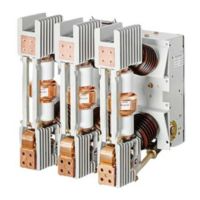
Figure 5: Stored-energy operating mechanism (circuit breaker shown in OPEN position) (straight linkage shown)
Item Description Item Description
50.2 Charging mechanism gear box 62.1 Charging shaft
50.3 Charging flange 62.2 Crank
50.3.1 Driver (not visible) 62.3 Cam disc
50.4 Spring charging motor 88.0 62.5 Lever
50.4.1 Limit switches 62.5.1 Pawl roller (not visible)
50.5 Manual spring-charging port 62.5.2 Close latch pawl
53.0 Close pushbutton 62.6 Driver lever
53.1 Close coil 52SRC 62.8 Straight coupling rod
1
54.0 Open pushbutton 62.8.1 Spring return latch (not shown)
1
54.1 Trip coil 52T 62.8.3 Trip-free coupling lever
1
55.0 Closing spring-charge indicator 63.0 Jack shaft
55.1 Linkage 63.1 Lever phase C
55.2 Control lever 63.5 Lever phase B
58.0 CLOSED/OPEN indicator 63.7 Lever phase A
59.0 Operations counter 64.0 Opening spring
60.0 Operator housing 68.0 Auxiliary switch
61.8 Shock absorber
68.1 Auxiliary switch link
62.0 Closing spring
50.2
Footnote:
1.
For certain applications, the
straight trip coupling rod (62.8) is
replaced by a collapsible trip-free
coupling system, illustrated in
Figures 6-10.
50.5
55.2
50.3
62.6
62.3
62.5
68.0
62.5.2
53.0
53.1
54.1
54.0
68.1
63.163.0
63.5
61.8
60.0
59.0
58.0
64.0
50.4
55.0
50.4.1
62.0
55.1
62.2
62.1

 Loading...