53
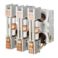
Table 12:Type 3AH vacuum circuit breaker ratings (historic "constant MVA" ratings basis)
4.
Within the limitations stated in
ANSI/IEEE C37.04-1979, all values apply to
polyphase and line-to-line faults. For single
phase-to-ground faults, the specific conditions
stated in clause 5.10.2.3 of
ANSI/IEEE C37.04-1979 apply.
5.
Current values in this row are not to be exceeded
even for operating voltage below 1/K times rated
maximum design voltage. For operating voltages
between rated maximum design voltage and 1/K
times rated maximum design voltage, follow
Footnote 5.
6.
Current values in this row are independent of
operating voltage up to and including rated
maximum voltage.
7.
"Nominal three-phase MVA class" is included for
reference only. This information is not listed in
ANSI C37.06-1987.
8.
Standard duty cycle is O - 15 s - CO.
9.
Standard rating interrupting time is five-cycles
(83 ms). Optional rated interrupting time of
three-cycles (50 ms) is available (except with
24 Vdc tripping).
These ratings are in
accordance with:
ANSI/IEEE C37.04-1979
Standard Rating Structure
for AC High-Voltage Circuit
Breakers Rated on a
Symmetrical Current Basis
ANSI C37.06-1987 AC
High-Voltage Circuit
Breakers Rated on a
Symmetrical Current Basis -
Preferred Ratings and
Related Required
Capabilities
ANSI/IEEE C37.09-1979
Standard Test Procedure for
AC High-Voltage Circuit
Breakers Rated on a
Symmetrical Current Basis
ANSI/IEEE C37.010-1979
Application Guide for AC
High-Voltage Circuit
Breakers Rated on a
Symmetrical Current Basis.
Circuit
breaker type
Nominal
voltage
class
Nominal
three-
phase
MVA
class
7
Maximum
design
voltage
(V)
1
Continuous
current
11
Voltage
range
factor
(K)
2
Withstand voltage
levels
kV MVA kV rms A rms ----
Power
frequency
kV rms
Lightning
impulse
(BIL)
kV crest
5-3AH-250,
5-3AHc-250
4.16 250 4.76 1,200, 2,000 1.24 19 60
5-3AH-350,
5-3AHc-350
4.16 350 4.76
1,200,
2,000, 3,000
1.19 19 60
7-3AH-500 7.2 500 8.25
1,200,
2,000, 3,000
1.25 36 95
15-3AH-500 13.8 500 15.0
1,200,
2,000, 3,000
1.30 36 95
15-3AH-750 13.8 750 15.0
1,200,
2,000, 3,000
1.30 36 95
15-3AH-1000 13.8 1000 15.0
1,200,
2,000, 3,000
1.30 36 95
38-3AH-1500 38.0 1,500 38.0 1,200, 2,000 1.65 80 150
Footnotes:
1.
Maximum design voltage for which the circuit
breaker is designed and the upper limit for
operation.
2.
K is the ratio of the rated maximum design
voltage to the lower limit of the range of
operating voltage in which the required
symmetrical and asymmetrical interrupting
capabilities vary in inverse proportion to the
operating voltage.
3.
To obtain the required symmetrical interrupting
capability of a circuit breaker at an operating
voltage between 1/K times rated maximum
design voltage and rated maximum design
voltage, the following formula shall be used:
Required symmetrical interrupting capability =
rated short-circuit current (I) x [(rated maximum
design voltage)/(operating voltage)]. For
operating voltages below 1/K times maximum
design voltage, the required symmetrical
interrupting capability of the circuit breaker shall
be equal to K times rated short-circuit current.
10.
High close and latch
(momentary) rating available for
special application.
11.
Continuous current may be
increased by the use of forced-
cooling (fan-cooling) in the
switchgear, together with
increased bus bar capacity.

 Loading...