A5E03804200A DS02 Seite 2 von 3 page 2 of 3
DALI
+ -
A
B+ -
A
B
: FAILURE
d: DIRECT
b: BUS
: VERSION
s
5WG1 141-1AB31
GAMMA
instabus
KNX / DALI Gateway Twin
50-60 Hz
A B
N L
max
I =200mA
Un 120 - 240 V
Un 110 - 240 V
B
F: FAILURE
d: DIRECT
b: BUS
UI: VERSION
A3
A4
A8
A7
A6
A5
A10
A11
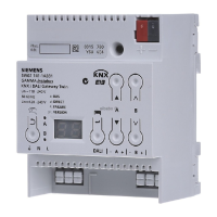
Bild / Figure 2
Lage und Funktion der Anzeige- und Bedienelemente
siehe Bild 2
A1 Programmiertaste mit LED (rot) zum Umschalten in den
Programmiermodus zur Übernahme der physikalischen
Adresse und zur Anzeige Normalmodus (LED Aus) oder
Programmiermodus (LED Ein).
A2 Stecker für KNX-Anschlussklemme
A3 Taste bei Betätigung
Kurz: „zurück“ Lang: Direktbetrieb
A4 Diese beiden LED dienen zur Anzeige der Information
des jeweiligen Kanals.
A5 Geräteinfo-Anzeige
A6 Taste bei Betätigung
„OK“ bzw. Menü
A7 Tastenpaar für Menüsteuerung bzw.
Direktbetrieb Kanal A
A8 Tastenpaar für Untermenüsteuerung bzw.
Direktbetrieb Kanal B
A9 Anschlussklemmen für Erd-, Neutral- und
Phasenleiter (L, N, Erde)
A10 Anschlussklemmenpaar für DALI Kanal A
A11 Anschlussklemmenpaar für DALI Kanal B
A12 Abisolierschablone (Prägung)
Geräteinfo-Anzeige
a) Statusanzeige
Modus Anzeige Beschreibung
Fehler
Anzeige
blinkt
88
An den DALI-Klemmen A9 bzw. A10
wurde Fremdspannung erkannt.
siehen unten:
Fremspannungserkennung
Fehler
(1.Stelle)
blinkend
F
Im Fehlerfall blinkt die Anzeige. Zu-
sätzlich wird an 1. Stelle „F“ ange-
zeigt zusammen mit dem aktuellen
Zeichen der 2. Stelle.
Fehleranzeige
Normalbe-
trieb
(2. Stelle)
b
Im Normalbetrieb (Busbetrieb) wer-
den alle Telegramme über KNX ge-
sendet.
Direkt-
betrieb
(2.Stelle)
d
Im Direktbetrieb lassen sich alle über
die DALI-Busleitung angeschlossen
EVG mit den Tastenpaaren A7/A8
schalten und dimmen. Der Schaltzu-
stand der Kanäle wird über die LED
A4 angezeigt.
Stand-alone
Betrieb
(2. Stelle)
c
Bei parametriertem Stand-alone Be-
trieb arbeitet das Gerät selbständig
weiter, falls die Kommunikation mit
KNX unterbrochen ist.
b) Menüfunktionen
Durch Drücken von A6 „Menü“ lassen sich Informationen ab-
rufen. Die Auswahl erfolgt durch A7 . Mit Drücken von A6
„OK“ gelangt man weiter, mit A3 „zurück“. Nach ca. 5 min
wechselt die Anzeige automatisch zurück in die Statusanzeige.
Die Informationen werden durch die Tasten A7 in der ers-
ten und durch A8 in der zweiten Menüebene vor-
/zurückgeblättert.
b1) Fehleranzeige
Taste Anzeige Bemerkung
A6
F
Menü Fehleranzeige
A6
88
erster Fehler
Kanal bzw. DALI-Teilnehmer
(z.B. Kanal A)
A8
F5
mit A8 zum nächsten / vorherigen Feh-
lerdetail bei Kanalfehler:
F4
F4F4
F4 DALI Spannungsversorgung
F5
F5F5
F5 DALI Kurzschluss
F6
F6F6
F6 kein EVG gefunden
A7
36
mit A7 zum nächsten / vorherigen Feh-
ler, z.B. Kanal A, DALI-Teilnehmer 36
A8
FO
mit A8 zum nächsten / vorherigen Feh-
lerdetail bei EVG Fehler
F0
F0F0
F0 Leuchtmittel defekt
F1
F1F1
F1 EVG defekt
--
Wurden während der
Fehleranzeige alle Fehler behoben er-
scheint beim weiter oder zurückschal-
ten in den Fehlercodes Alle Fehler be-
hoben
A3
Mit „zurück“ verlässt man die Anzeige
und gelangt zum Menü
Location and Function of the Display and Operating Elements
see figure 2
A1 Programming key with LED (red) for switching in pro-
gramming mode to accept the physical address and to
display normal mode (LED Off) or programming mode
(LED On).
A2 Plug for KNX terminal
A3 Operating key
Tap: "back" Hold down: Direct mode
A4 Both these LEDs display information about the relevant
channel.
A5 Device info display
A6 Operating key
"OK" and Menu
A7 Key pair for menu control and
direct mode channel A
A8 Key pair for sub-menu control and
direct mode channel B
A9 Terminals for ground, neutral and phase lines (L, N,
ground)
A10 Terminal pair for DALI channel A
A11 Terminal pair for DALI channel B
A12 Stripping template (stamping)
Device info-Display
a) Status indication
Mode Indication Description
Error
Display
flashes
88
Incorrect voltage detected at DALI
terminals A9 and A10.
see below:
Incorrect voltage detection
Error
(1
st
position)
flashing
F
The display flashes if there is an er-
ror. "F" is also displayed in the 1
st
position together with the current
symbol for the 2
nd
position. see
below Error indication
Normal
mode
(2
nd
position)
b
In normal mode (bus mode), all tele-
grams are sent via KNX.
Direct mode
(2
nd
position)
d
In direct mode, all ECGs connected
via the DALI bus line can be
switched and dimmed with the key
pair A7/A8. The LED A4 indicates the
switching status.
Standalone
mode
(2
nd
position)
c
If standalone mode is configured,
the device continues to work inde-
pendently if communication with
KNX is interrupted.
b) Menu functions
Pressing A6 "Menu" calls up information. Selection is per-
formed by A7 . Press A6 "OK" to continue, press A3
for "back". After approximately 5 min, the display reverts auto-
matically to status display. The information is scrolled up and
down with the A7 keys in the first level and with the A8
keys in the second menu level.
b1) Error indication
Key Indication Note
A6
F
Error indication menu
A6
88
First error
Channel or DALI subscriber
(e.g. channel A)
A8
F5
Use A8 to scroll to the next/previous
error detail for channel error:
F4
F4F4
F4 DALI voltage supply
F5
F5F5
F5 DALI short circuit
F6
F6F6
F6 No ECG found
A7
36
Use A7 to scroll to next/previous error,
e.g. channel A, DALI subscriber 36
A8
FO
Use A8 to scroll to next/previous error
details with ECG error
F0
F0F0
F0 Illuminant defective
F1
F1F1
F1 ECG defective
--
All errors were corrected during the er-
ror indication on continuing or switch-
ing back into the error codes
A3
Use "back" to quit the display and re-
turn to the menu
A12
 Loading...